Systems and Methods for Providing an Array Projector

Inactive Publication Date: 2014-09-18
FOTONATION CAYMAN LTD
View PDF5 Cites 148 Cited by
  • Summary
  • Abstract
  • Description
  • Claims
  • Application Information

AI Technical Summary

Benefits of technology

[0012]In accordance with some embodiments of the invention, the processing system applies photometric correction data to the low resolution image data provided to each of the projection components to correct for photometric errors in each of the projection components. In accordance with many embodiments, the processing system applies geometric correction data to the low resolution image data provided to each of the projection components to correct for geometric errors in each of the projection components. In accordance with many embodiments, the processing systems applies translation data to the low resolution data provided to each of the projection components to configure corresponding pixel projections in the projection components to produce a desired higher resolution image at a given projection distance.
[0013]In accordance with some embodiments, the application of the inverse super resolution algorithms includes determining and applying parallax correction for each of the projection components for a given projection distance that includes radical shifts at one of a level selected a sub-pixel level, a pixel level, and a larger than pixel level based upon the projection distance and a position of a channel in a particular projection component in the array. In accordance with many embodiments, the applying of the inverse super resolution processing algorithms includes determining for each of the projection components and applying the inverse super resolution correction data to the lower resolution image data for each of the plurality of projection components to cause an increased resolution in the physic

Problems solved by technology

A problem common in the projection of images onto a surface is the provision of high resolution images.
The resolution of a projector is often limited by the physical constraints of the projection components (e.g. pixel size of the display) and the lens assembly used to project the image onto a surface.
In spite of the high resolution of this approach, due to the small pixel/feature size in the transparencies, the approach is not very attractive, since the projected image cannot be dynamically changed.
It shoul

Method used


Image

  • Systems and Methods for Providing an Array Projector
  • Systems and Methods for Providing an Array Projector
  • Systems and Methods for Providing an Array Projector

Examples


Embodiment Construction

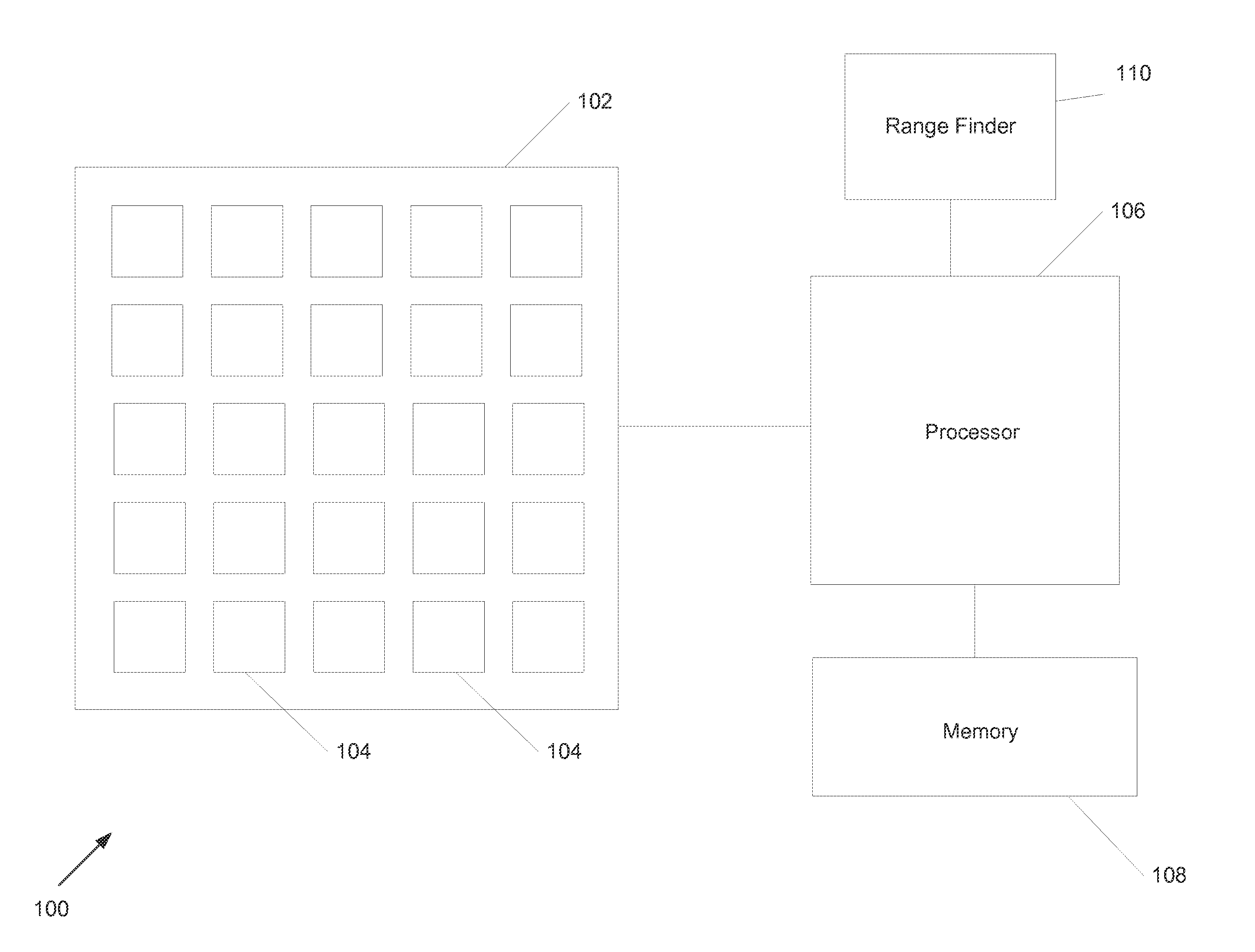
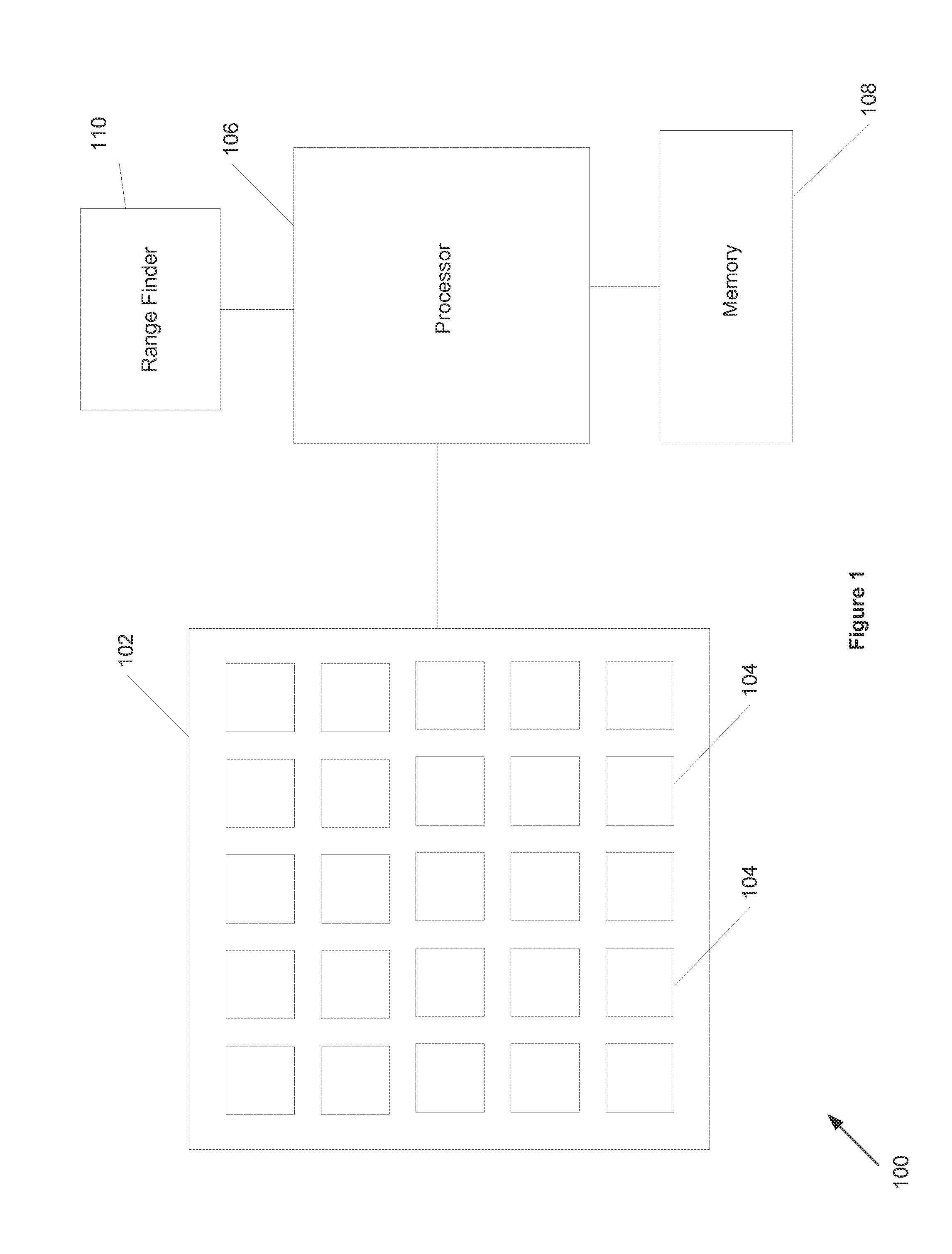
[0024]Turning now to the drawings, systems and methods for providing an array projector in accordance with embodiments of the invention are illustrated. In accordance with many embodiments of this invention, an array projector system includes an array projector module and a processing system that performs processes used in projecting images using the array projection module. The array projector module includes an array of projection components. Each projection component includes a digital display device and a lens arrangement. In operation, each of the digital display devices generates a suitably pre-processed downsampled image that is downsampled from an initial high resolution image and the downsampled images is projected by a lens arrangement onto a common area of a surface or object at a certain projection distance such that the combination of the projected downsampled images results in a higher resolution projected image. In accordance with some embodiments, the following proce...


PUM


Abstract

Embodiments of systems and methods for providing an array projector are disclosed. The array projector includes an array of projection components and an image processing system. Each of the projection components projects a lower resolution image onto a common surface area and the overlapping lower resolution image combine to form a higher resolution image. The image processor provides lower resolution image data to each of the projection components in the array. The lower resolution image data is generated using the image processor by applying super resolution algorithms lower resolution image data received by the image processor.

Description

CROSS-REFERENCE TO RELATED APPLICATIONS[0001]The current application claims priority to U.S. Provisional Patent Application No. 61 / 801,733, filed Mar. 15, 2013, the disclosure of which is incorporated herein by reference.FIELD OF THE INVENTION[0002]This invention relates to the projection of images. More particularly, this invention relates to the projection of low resolution images from an array of projectors to produce a single higher resolution image.BACKGROUND[0003]A problem common in the projection of images onto a surface is the provision of high resolution images. The resolution of a projector is often limited by the physical constraints of the projection components (e.g. pixel size of the display) and the lens assembly used to project the image onto a surface. This is particularly true of a projector that is small enough in size to fit into a mobile device such as smart phone, laptop, touch touchpad or other common mobile device. The size needed to place a projector in a mob...

Claims


Application Information

Patent Timeline
IPC IPC(8): G06T5/00
CPCG06T5/00G06T3/4053G09G3/002G09G2320/0242G09G2320/0693G09G2340/0407G09G2340/0457H04N9/3188H04N9/3194H04N13/243
Inventor DUPARRE, JACQUES
Owner FOTONATION CAYMAN LTD
Why Eureka
Try Eureka