Apparatus and method for providing failed-attempt feedback using a camera on glasses
Active Publication Date: 2014-09-18
ORCAM TECH
View PDF5 Cites 15 Cited by
Summary
Abstract
Description
Claims
Application Information
AI Technical Summary
This helps you quickly interpret patents by identifying the three key elements:
Problems solved by technology
Method used
Benefits of technology
Benefits of technology
The patent text describes devices and methods for providing information to users by processing images of their environment. The technology may be useful for people with low vision.
Problems solved by technology
Other than eye damage and failure of the brain to receive visual cues sent by the eyes, different medical conditions may cause visual impairment.
There is no cure for retinitis pigmentosa and no known treatment can stop the progressive vision loss caused by the disease.
A cataract is a clouding of the lens inside the eye which leads to a decrease in vision.
People with low vision experience difficulties due to lack of visual acuity, field-of-view, color perception, and other visual impairments.
These difficulties affect many aspects of everyday life.
However, magnifying glasses are expensive and cannot remedy all aspects of low vision.
For example, a person with low vision who wears magnifying glasses may still have a difficult time recognizing details from a distance (e.g., people, signboards, traffic lights, etc.).
Method used
Image
Click on the blue label to locate the original text in one second.
Reading with bidirectional positioning of images and text.
Examples
first embodiment
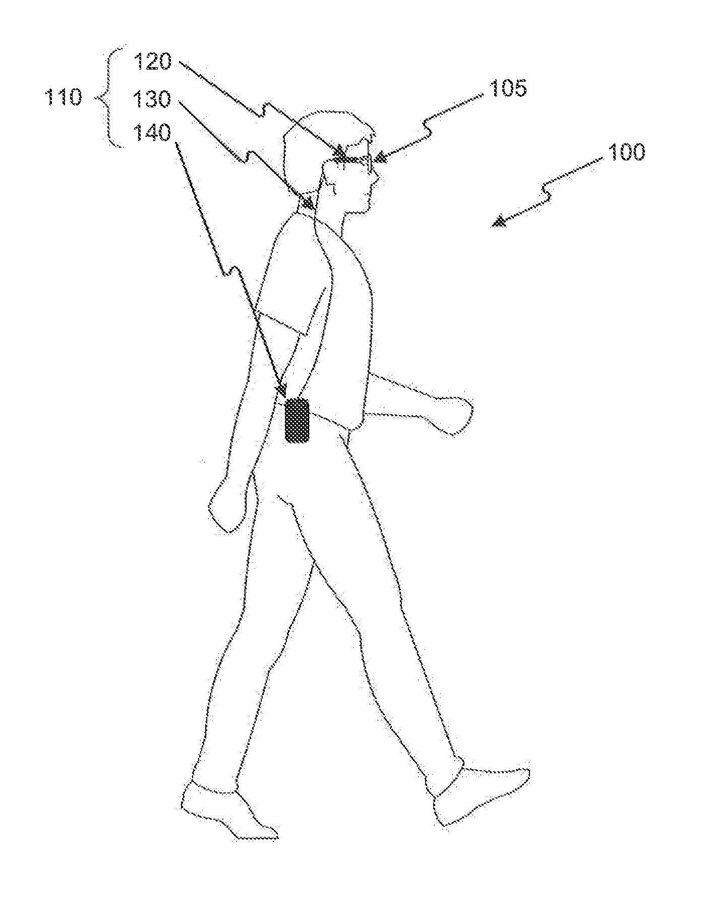
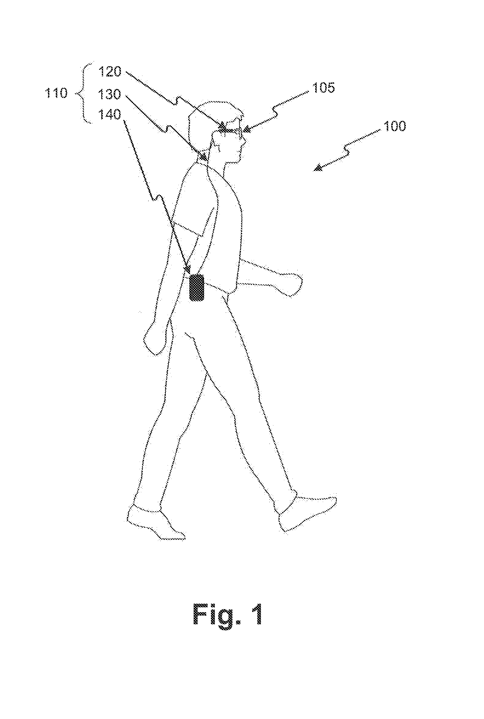
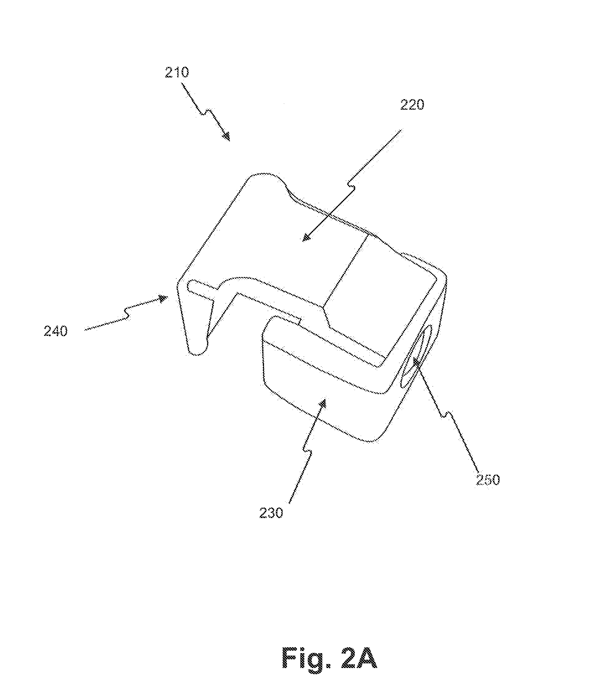
[0071]FIG. 5A is a block diagram illustrating the components of apparatus 110 according to a Specifically, FIG. 5A depicts an embodiment in which apparatus 110 comprises sensory unit 120 and processing unit 140, as discussed in connection with, for example, FIG. 1. Furthermore, sensory unit 120 may be physically coupled to support 210.
[0072]As shown in FIG. 5A, sensory unit 120 includes feedback-outputting unit 340 and image sensor 350. Although one image sensor is depicted in FIG. 5A, sensory unit 120 may include a plurality of image sensors (e.g., two image sensors). For example, in an arrangement with more than one image sensor, each of the image sensors may be face a different direction or be associated with a different camera (e.g., a wide angle camera, a narrow angle camera, an IR camera, etc.). In other embodiments (not shown in the figure) sensory unit 120 may also include buttons and other sensors such as a microphone and inertial measurements devices.
[0073]As further show...
second embodiment
[0082]FIG. 5B is a block diagram illustrating the components of apparatus 110 according to a In FIG. 5B, similar to the arrangement shown in FIG. 5A, support 210 is used to couple sensory unit 120 to a pair of glasses. However, in the embodiment shown in FIG. 5B, sensory unit 120 and processing unit 140 communicate wirelessly. For example, wirelesstransceiver 530A can transmit image data to processing unit 140 and receive information to be outputted via feedback-outputting unit 340.
[0083]In this embodiment, sensory unit 120 includes feedback-outputting unit 340, mobile power source 510A, wirelesstransceiver 530A, and image sensor 350. Mobile power source 510A is contained within sensory unit 120. As further shown in FIG. 5B, processing unit 140 includes wirelesstransceiver 530B, processor 540, mobile power source 510B, and memory 520.
third embodiment
[0084]FIG. 5C is a block diagram illustrating the components of apparatus 110 according to a In particular, FIG. 5C depicts an embodiment in which support 210 includes image sensor 350 and connector 550B. In this embodiment, sensory unit 120 provides functionality for processing data and, therefore, a separate processing unit is not needed in such a configuration.
[0085]As shown in FIG. 5C, sensory unit 120 includes processor 540, connector 550A, mobile power source 510, memory 520, and wireless transceiver 530. In this embodiment, apparatus 110 does not include a feedback-outputting unit. Accordingly, wireless transceiver 530 may communicate directly with a hearing aid (e.g., a Bluetooth® hearing aid). In addition, in this embodiment, image sensor 350 is included in support 210. Accordingly, when support 210 is initially mounted on glasses 105, image sensor 350 may acquire a set aiming direction. For example, a camera associated with image sensor 350 may be installed within support...
PUM
Abstract
Apparatuses and a method are provided for providing feedback to a user, who may be visually-impaired. In one implementation, a method is provided for providing feedback to a visually impaired user. The method comprises receiving from a mobile image sensor real time image data that includes a representation of an object in an environment of the visually impaired user. The mobile image sensor is configured to be connected to glasses worn by the visually impaired user. Further, the method comprises receiving a signal indicating a desire of the visually impaired user to obtain information about the object. The method also includes accessing a database holding information about a plurality of objects, and comparing information derived from the received real time image data with information in the database. The method comprises providing the visually impaired user with nonvisual feedback that the object is not locatable in the database.
Description
CROSS REFERENCE TO RELATED APPLICATIONS[0001]This application claims the benefit of priority of U.S. Provisional Patent Application No. 61 / 799,649, filed on Mar. 15, 2013, and U.S. Provisional Patent Application No. 61 / 830,122, filed on Jun. 2, 2013, both of which are incorporated herein by reference in their entirety.BACKGROUND[0002]I. Technical Field[0003]This disclosure generally relates to devices and methods for providing information to a user. More particularly, this disclosure relates to devices and methods for providing information to a user by processing images captured from the environment of the user.[0004]II. Background Information[0005]Visual acuity is an indication of the clarity or clearness of a person's vision that is commonly measured twenty feet from an object. When measuring visual acuity, the ability of a person to identify black symbols on a white background at twenty feet is compared to the ability of a person with normal eyesight. This comparison can be symbo...
Claims
Application Information
Patent Timeline
Application Date:The date an application was filed.
Publication Date:The date a patent or application was officially published.
First Publication Date:The earliest publication date of a patent with the same application number.
Issue Date:Publication date of the patent grant document.
PCT Entry Date:The Entry date of PCT National Phase.
Estimated Expiry Date:The statutory expiry date of a patent right according to the Patent Law, and it is the longest term of protection that the patent right can achieve without the termination of the patent right due to other reasons(Term extension factor has been taken into account ).
Invalid Date:Actual expiry date is based on effective date or publication date of legal transaction data of invalid patent.

