
Apparatus, system, and method of inspecting image, and computer-readable medium storing image inspection control program

a technology of image inspection and system, applied in the direction of instrumentation, colour separation/tonal correction, photomechanical treatment, etc., can solve the problems of inefficiency of comparing the master image generated from previously printed matter with the printed matter, and not disclose the calculation method in detail,

Inactive Publication Date: 2014-09-18
RICOH KK
View PDF20 Cites 16 Cited by
  • Summary
  • Abstract
  • Description
  • Claims
  • Application Information

AI Technical Summary

Benefits of technology

The patent describes an information processing system that can obtain a scan of a printed image to determine the output characteristics of the printing machine. The system uses a set of different color dots to calculate the density of each pixel in the image and calculates a filter to adjust for any differences in output between pixels. This results in a more accurate representation of the printed image and improves the overall quality of the finished product. The system is designed to make it easy to obtain and process images from different printing machines, and can even adjust for different environmental factors that may affect the printing process. This patent is useful for anyone who needs to produce accurate and high-quality printed images.

Problems solved by technology

In such a case, comparing the printed matter, with a master image generated from previously printed matter, would be inefficient.
Although JP 2011-156861-A discusses a method of calculating in advance the dot gain (i.e., the output characteristics for each pixel) for each of the kinds of sheets, it does not disclose the method of the calculating in detail.
In addition, such a problem can equally occur for other recording media such as films, not only to the case of outputting an image to paper.

Method used


Image

  • Apparatus, system, and method of inspecting image, and computer-readable medium storing image inspection control program
  • Apparatus, system, and method of inspecting image, and computer-readable medium storing image inspection control program
  • Apparatus, system, and method of inspecting image, and computer-readable medium storing image inspection control program

Examples


Embodiment Construction

[0033]The terminology used herein is for the purpose of describing particular embodiments only and is not intended to be limiting of the present embodiments. As used herein, the singular forms “a”, “an” and “the” are intended to include the plural forms as well, unless the context clearly indicates otherwise. It will be further understood that the terms “includes” and / or “including”, when used in this specification, specify the presence of stated features, integers, steps, operations, elements, and / or components, but do not preclude the presence or addition of one or more other features, integers, steps, operations, elements, components, and / or groups thereof.

[0034]In describing example embodiments shown in the drawings, specific terminology is employed for the sake of clarity. However, the present disclosure is not intended to be limited to the specific terminology so selected and it is to be understood that each specific element includes all technical equivalents that operate in a...


PUM


Abstract

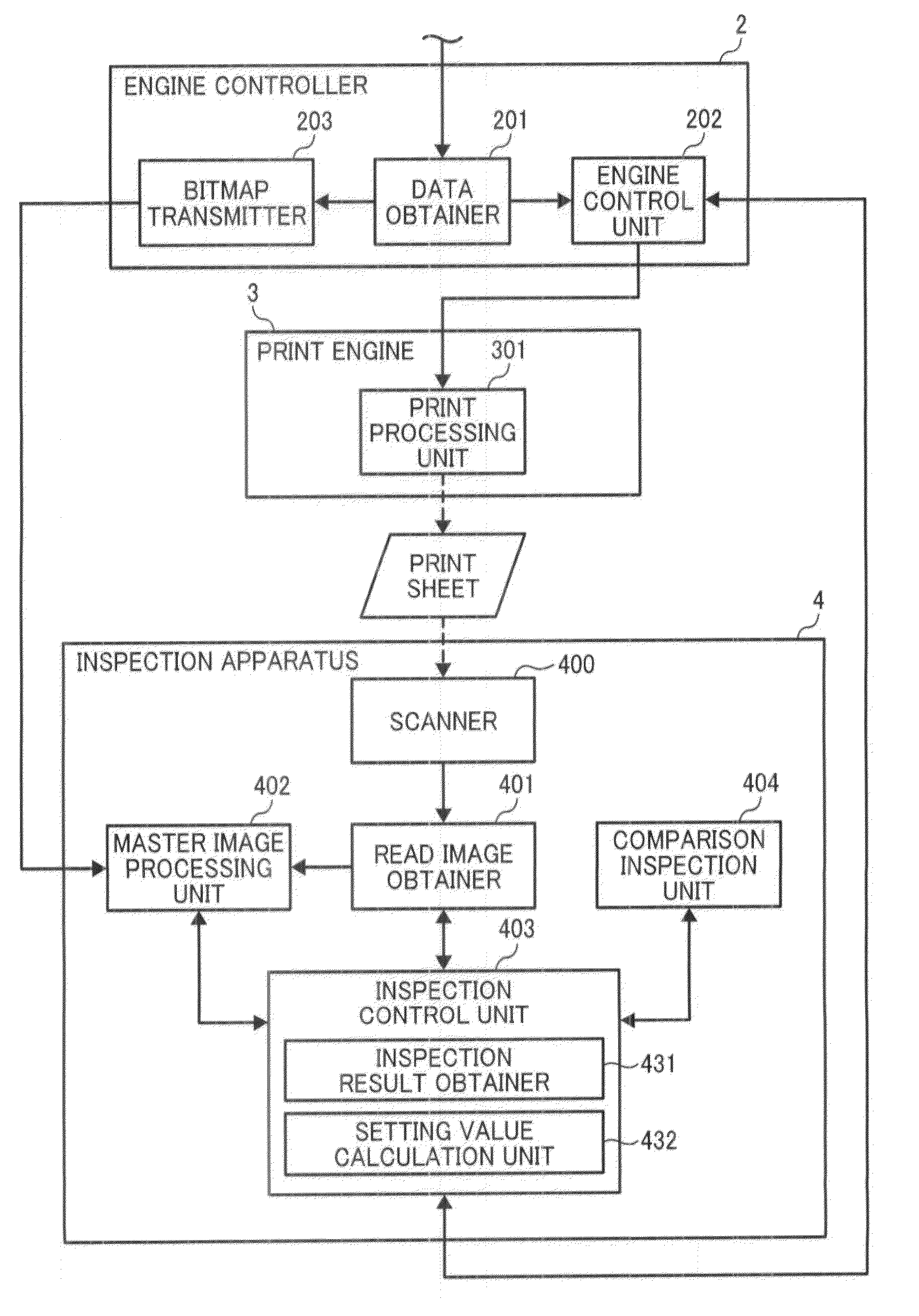
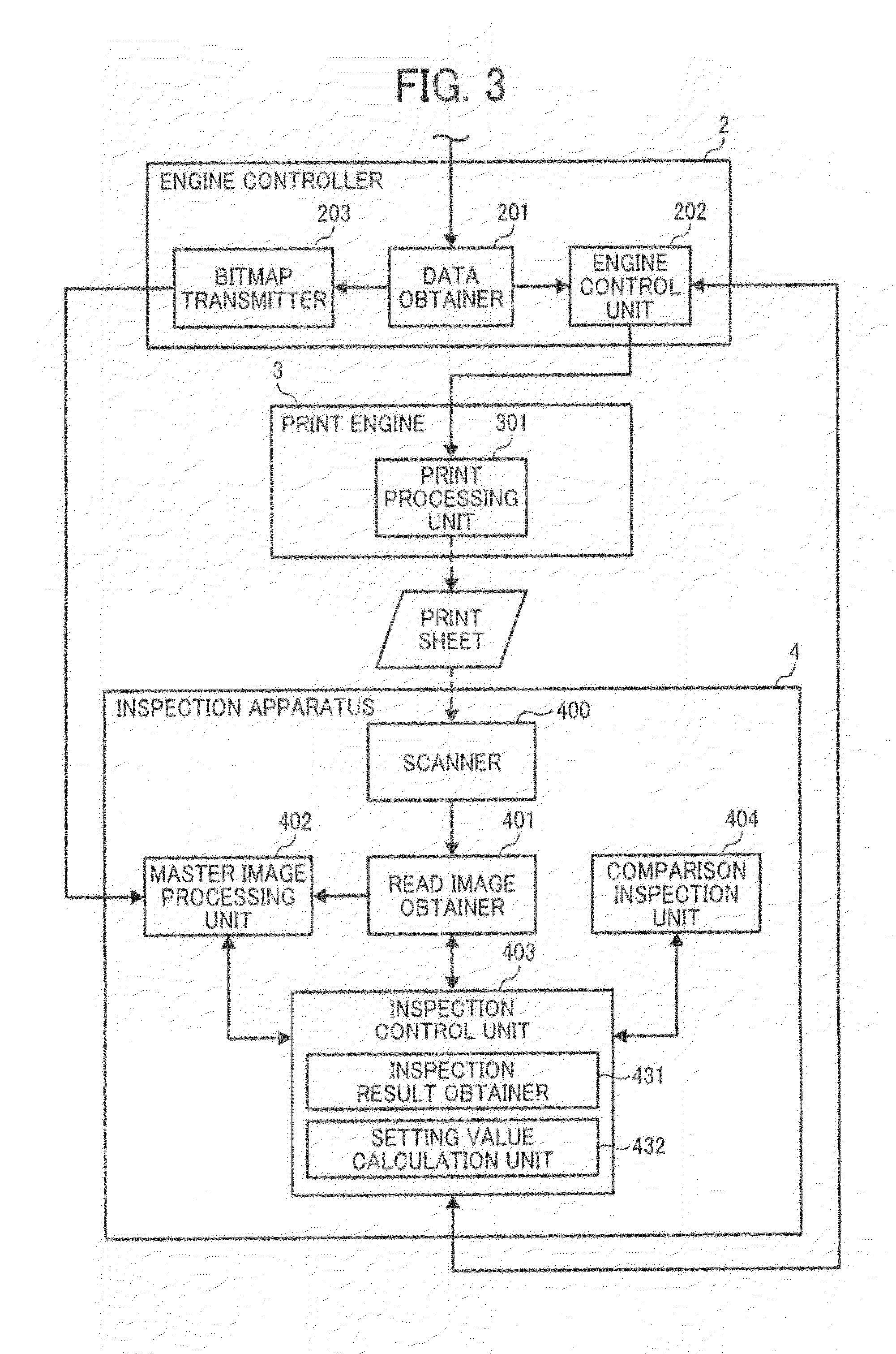
An information processing apparatus including a read image obtainer and a setting value calculator implemented by circuitry. The read image obtainer obtains a scanned determination image, including a plurality of different dot patterns output by an image forming apparatus on a recording medium. The setting value calculator, for each of the different dot patterns of the obtained scanned determination image, determines densities of different colors of the respective dot pattern and a total number of pixels influencing the density of each coefficient of a dot gain correction filter, with respect to each target pixel. The setting value calculator further configured calculates the coefficients of the dot gain correction filter based on the determined densities of the different colors of the different dot patterns and the total number of pixels, determined for each coefficient of the dot gain correction filter and for each of the different dot patterns.

Description

CROSS-REFERENCE TO RELATED APPLICATIONS[0001]This patent application is based on and claims priority pursuant to 35 U.S.C. §119 to Japanese Patent Application Nos. 2013-053999, filed on Mar. 15, 2013, and 2014-023245, filed on Feb. 10, 2014, in the Japan Patent Office, the entire disclosures of which are hereby incorporated by reference herein.BACKGROUND[0002]1. Field of the Invention[0003]The present disclosure relates to an apparatus, system, and method of inspecting an image formed by an image forming apparatus, and a non-transitory computer-readable medium storing an image inspection control program.[0004]2. Description of the Related Art[0005]Conventionally, inspection of printed matter has been performed by human operators. In recent years, inspection apparatuses that automatically inspect printed matter have been widely used, mainly in the field of offset printing. For example, in conventional devices, a master image would be generated by reading specific printed matter that ...

Claims


Application Information

Patent Timeline
Patent Type & Authority Applications(United States)
IPC IPC(8): H04N1/60
CPCH04N1/6027H04N1/6038
Inventor KITAI, TADASHIFUKASE, TAKAHIRO
Owner RICOH KK
Learn More