
Modulated cooling flow scheduling for both sfc improvement and stall margin increase

a cooling flow and module technology, applied in the field of modules, can solve the problems of compromising the stall margin at high power operation, excessive cooling provided, adversely affecting the sfc,

Active Publication Date: 2014-09-18
ROLLS ROYCE CORP
View PDF8 Cites 11 Cited by
  • Summary
  • Abstract
  • Description
  • Claims
  • Application Information

AI Technical Summary

Benefits of technology

The patent text describes an improved method of operating a gas turbine engine that reduces fuel consumption and improves overall specific fuel consumption (SFC) while not compromising stall margin. The method involves controlling coolant flow within the engine to optimize SFC without sacrificing stall margin. By modulating valves and interposing airflow lines, the method achieves better cooling efficiency and reduces excess cooling airflow during certain operating conditions. This allows for a more favorable trade-off between SFC and stall margin, resulting in improved engine performance. The patent also describes a computer-readable storage medium with corresponding control instructions for the gas turbine engine.

Problems solved by technology

Thus, for part power operation (e.g., cruise), as an example, excess cooling is provided adversely impacting SFC.
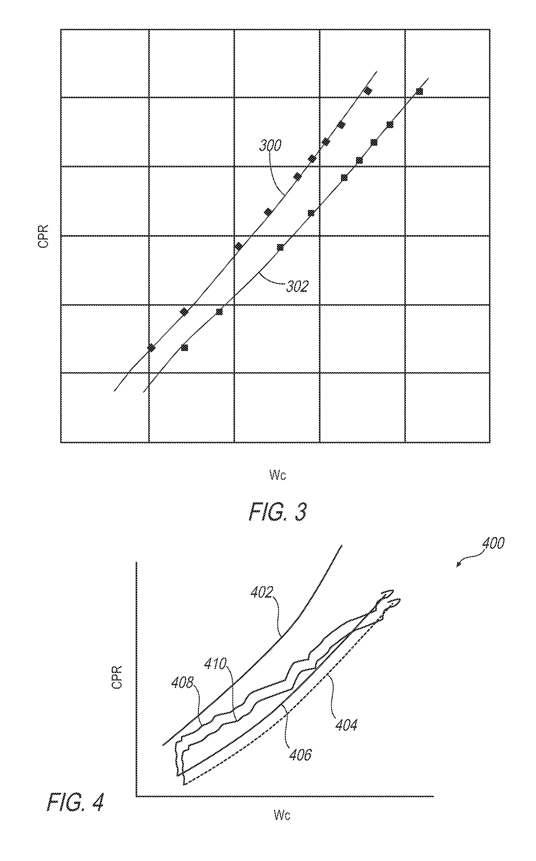
However, coolant airflow based on cruising requirements would compromise stall margin at high power operation and during engine acceleration (including hot re-slam or bodie) if the amount of coolant airflow is not increased to the level existing at high power.

Method used


Image

  • Modulated cooling flow scheduling for both sfc improvement and stall margin increase
  • Modulated cooling flow scheduling for both sfc improvement and stall margin increase
  • Modulated cooling flow scheduling for both sfc improvement and stall margin increase

Examples


Embodiment Construction

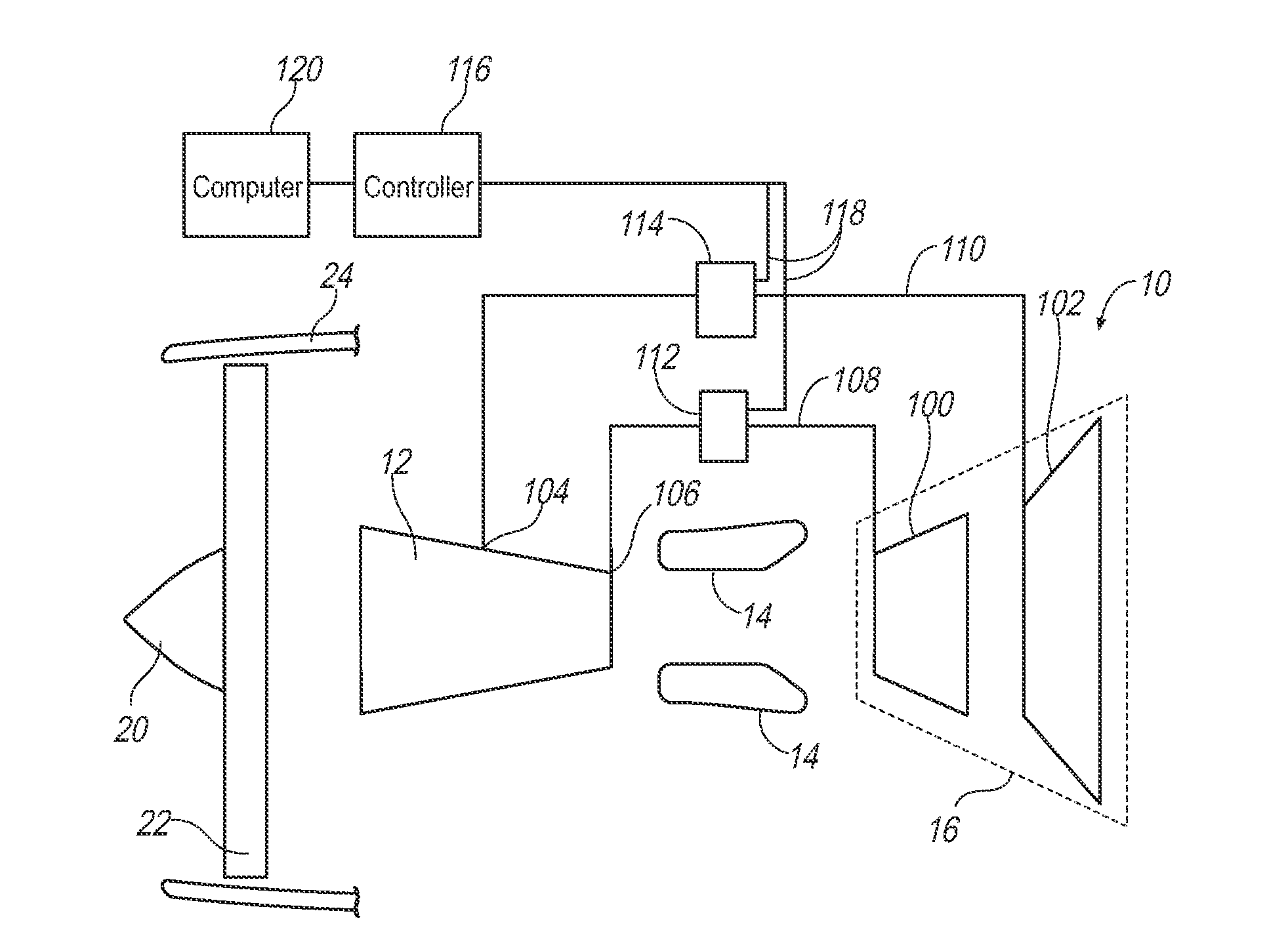
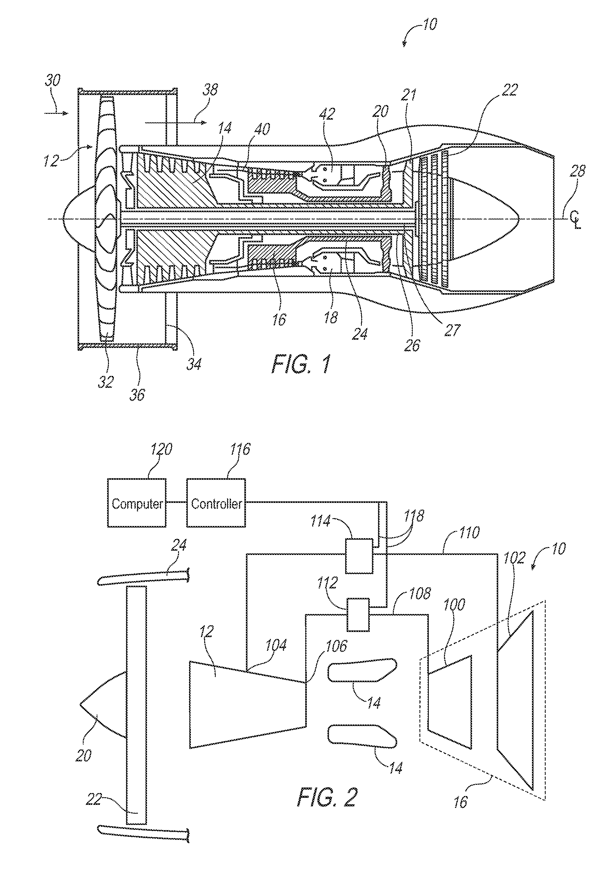
[0016]An exemplary gas turbine and an exemplary control scheme for the gas turbine are described herein and are shown in the attached drawings. The gas turbine engine includes a compressor having a mid-compression pressure station and an exit pressure station, and low and high pressure turbines. Airflow lines and respective valves are interposed between the compressor and the turbine sections and controlled to operate based on an operating condition of the turbine engine.

[0017]Another exemplary illustration includes providing a method of operating a turbine engine and a computer readable storage medium having corresponding control instructions. The method includes modulating valves of the turbine engine based on an operating condition of the turbine engine, wherein the valves are coupled to respective coolant lines that are interposed between sections of a compressor and a turbine. Such an arrangement could eliminate the need for a separate low compressor bleed which is used in lega...


PUM


Abstract

A turbine engine includes a compressor, and high and low pressure turbines. The configuration includes a mid-compression station which can be, in the case of a single compressor in the middle of that compressor, or at the exit of the first compressor in the case of two compressors. Also, there is an exit pressure station at the exit of the compression system. A first gas flow line is interposed between the mid-compression station of the compressor and the low pressure turbine, and a second gas flow line is interposed between the exit pressure station of the compression system and the high pressure turbine. A first valve is coupled to the first gas flow line and modulates a low pressure flow rate of coolant in the first gas flow line, and a second valve is coupled to the second gas flow line and modulates a high pressure flow rate of coolant in the second coolant flow line. A controller is configured to operate the first and second valves based on an operating condition of the turbine engine so as to improve the specific fuel consumption while ensuring acceptable stall margin.

Description

CROSS-REFERENCE TO RELATED APPLICATIONS[0001]This application claims priority to U.S. Provisional Patent Application No. 61 / 780,873, filed Mar. 13, 2013, the contents of which are hereby incorporated in their entirety.FIELD OF TECHNOLOGY[0002]An improved method of operating a gas turbine is disclosed, and more particularly, an improved method of controlling coolant flow within the gas turbine to improve overall specific fuel consumption (SFC) while not compromising stall margin.BACKGROUND[0003]It has become increasingly desirable to reduce fuel consumption and improve overall SFC in a gas turbine. At the same time it is desirable to improve SFC without compromising on stall margin during all conditions of turbine engine operation.[0004]Stall, or otherwise commonly known as surge, occurs when a compressor operating point / line rises to its stability limit that defines a limit between stable and unstable regions of flow. Below the limit, flow is stable, and a distance to the surge line...

Claims


Application Information

Patent Timeline
IPC IPC(8): F04D27/00
CPCF04D27/002F02C9/18F05D2270/101F04D27/0246Y02T50/60
Inventor KHALID, SYED JALALUDDINGRITTON, MARK J.
Owner ROLLS ROYCE CORP
Learn More