Work vehicle HVAC control based on operator seat direction

a technology for controlling the hvac system of the work vehicle and the seat direction, which is applied in the direction of vessel parts, transportation and packaging, vessel construction, etc., can solve the problems of unsafe conditions, unnecessarily complex and expensive overbuilt systems, and unnecessary labor and distraction risk

Active Publication Date: 2014-09-18
DEERE & CO
View PDF21 Cites 8 Cited by
  • Summary
  • Abstract
  • Description
  • Claims
  • Application Information

AI Technical Summary

Benefits of technology

[0006]An HVAC control system, for an HVAC system of a work vehicle that has an operator's seat assembly which includes a seat that rotates between multiple operational positions, permits and restricts airflow through the HVAC system based on the position of the seat. One or more seat position detectors may be positioned to detect the position of the seat. The detectors may transmit data identifying the seat position to a control module. The control module may operate one or more HVAC system components, such as one or more doors, fans, or motors, to automatically modify airflow in response to the seat position data.
[0007]In this manner, when the operator rotates the seat from a first position to a second position, the detectors may report the position change to the control module, which may open, close, rotate, start, stop, or otherwise operate one or more of the HVAC system components to redirect airflow through the HVAC system air ducts and vents as needed to account for the second position of the seat.
[0008]Thus, in one aspect this disclosure provides: in a work vehicle having a seat that rotates between a first operational position and a second operational position, and further having an HVAC system having at least a first duct for directing air at a first area and a second duct for directing air at a second area distinct from the first area, a control system comprising: a first door that prevents air from flowing through the first duct in a closed position and allows air to flow through the first duct in an open position; a first actuator for moving the first door between at least the closed and open positions; a detector for detecting whether the seat is in at least one of the first and second operational positions and generating a position output signal based on the detected operational position; and a control module for driving the first actuator according to the position output signal of the detector.
[0009]In another aspect this disclosure provides: in a work vehicle having a cabin in which is disposed a seat assembly having a rotating seat, and further having an HVAC system with at least a first duct for delivering air through at least one vent to a first area of the cabin and a second duct for delivering air through at least one vent to a second area of the cabin distinct from the first area, an HVAC control system comprising: a door disposed in each duct and configured to move between a fully open position, allowing maximum flux of air into the duct, and a fully closed position that completely occludes the duct; a control module operatively coupled to each door to move the door between at least the fully open and fully closed positions; a marker configured to rotate with the seat; and at least one detector for detecting whether the seat is in a first operational position or a second operational position, the detector being electrically coupled to the control module for transmitting, to the control module, a position output signal indicating a position of the seat; wherein the control module moves the door of each duct according to the position output signal.
[0010]In another aspect this disclosure provides: in a work vehicle having a cabin in which is disposed a seat assembly having a rotating seat, and further having an HVAC system with a forward duct for delivering air through at least one vent to a front area of the cabin and a rearward duct for delivering air through at least one vent to a rear area of the cabin, an HVAC control system, comprising: a marker attached to a rotating structure within the seat assembly, the seat being mounted on the rotating structure; at least one detector attached to a stationary structure within the seat assembly that does not rotate with the seat, the detector being configured to detect a position of the marker and generate a position output signal that indicates the position of the seat; a first mode door assembly attached to the forward duct and comprising: a housing attached to the forward duct; a first mode door movably mounted within the housing; and an actuator attached to the housing and the first mode door for moving the first mode door between an open position that allows air into the forward duct and a closed position that occludes the forward duct; a second mode door assembly attached to the rearward duct and comprising: a housing attached to the rearward duct; a second mode door movably mounted within the housing; and an actuator attached to the housing and the second mode door for moving the second mode door between an open position that allows air into the forward duct and a closed position that occludes the forward duct; and a control module electrically connected to the detector for receiving the position output signal, and electrically connected to each of the first and second actuators to drive the actuators to move each of the first and second mode doors in response to the position output signal; wherein the position of the seat may comprise a first operational position or a second operational position.

Problems solved by technology

To account for all operational positions of the seat, HVAC systems for such work vehicles may be designed to provide all functionality for all seat positions at all times. Such an overbuilt system is unnecessarily complex and expensive, and is inefficient due to its provision of HVAC functionality where it is not needed.
This is also inefficient, adds labor and risk of distraction, and may cause unsafe conditions if the operator does not properly adjust the controls.

Method used


Image

  • Work vehicle HVAC control based on operator seat direction
  • Work vehicle HVAC control based on operator seat direction
  • Work vehicle HVAC control based on operator seat direction

Examples


Embodiment Construction

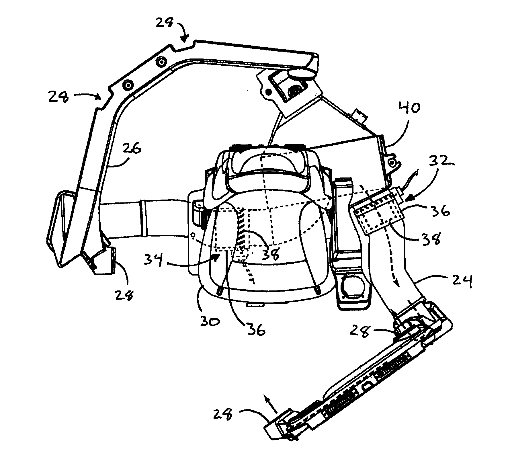
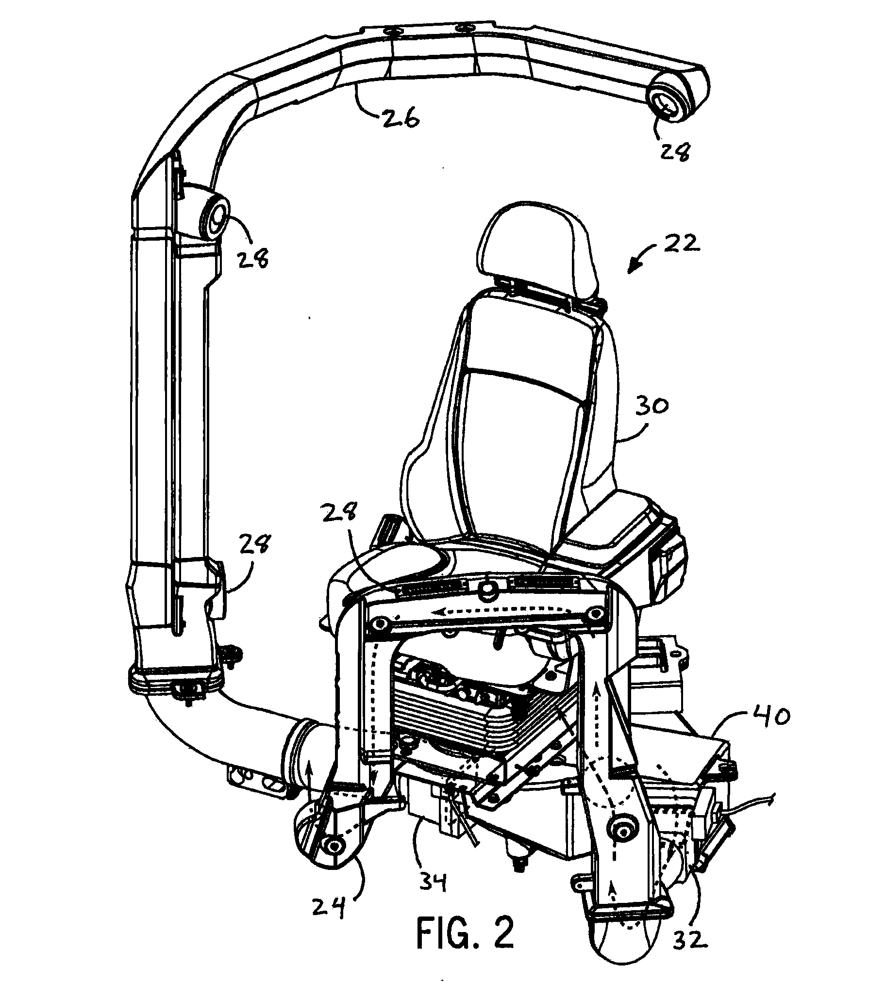
[0026]As shown in the accompanying figures of the drawings described above, the following describes one or more example constructions of an HVAC control system, which can be used to automatically control the airflow through an HVAC system of a work vehicle based on the position of the operator's seat. Various modifications to the example construction(s) may be contemplated by one of skill in the art.

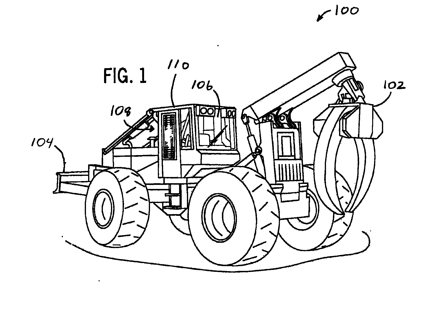
[0027]The HVAC control system may be used in any work vehicle wherein the rotation of the operator's seat renders some HVAC ventilation components useful and others extraneous or inefficient. FIG. 1 shows an example work vehicle 100 in which the HVAC control system may be advantageously used. The work vehicle 100 has a front implement 102 and a rear implement 104, and the operator sits in the cabin 110 and looks out the front windscreen 106 to operate the front implement 102 and the rear windscreen 108 to operate the rear implement 104. The HVAC control system may be utilized in various ...


PUM


Abstract

An HVAC control system for directing the flow of air in a work vehicle's HVAC system responds to the orientation of a rotating seat within the work vehicle's cabin. The seat may rotate between at least two operational positions, such that the operator of the work vehicle may control a forward or a rearward implement. The HVAC control system includes one or more detectors for detecting the position of the seat. A control module receives output from the detectors and allows or prevents the flow of air through particular ducts in the HVAC system based on the seat's position. The control module may actuate one or more doors to open and close ducts as needed. The control module may operate a first door to open or close forward ducts and a second door to open or close rearward ducts depending on whether the seat is facing forward or rearward.

Description

CROSS-REFERENCE TO RELATED APPLICATION(S)[0001]Not applicable.STATEMENT OF FEDERALLY SPONSORED RESEARCH OR DEVELOPMENT[0002]Not applicable.FIELD OF THE DISCLOSURE[0003]This disclosure relates to the heating, ventilation and air-conditioning (HVAC) systems of work vehicles, and in particular the control of HVAC systems based on operator seat positioning within the vehicle cabin.BACKGROUND OF THE DISCLOSURE[0004]Many types of construction implements, forestry vehicles, and other work vehicles include an operator's seat assembly that rotates between multiple operational positions to give the operator flexibility in performing tasks with the work vehicle. For example, a work vehicle may have front and rear implements, and the operator rotates his seat from a front-facing position for operating the front implement to a rear-facing position for operating the rear implement. To satisfy regulatory standards, it may be required to provide certain HVAC functionality within the vehicle cabin d...

Claims


Application Information

Patent Timeline
Patent Type & Authority Applications(United States)
IPC IPC(8): B60H1/00
CPCB60H1/00871B60H1/00742B60H1/00378
Inventor GUILLORY, CHRISBREINER, SCOTT J.HUBER, RONALD J.
Owner DEERE & CO
Why Eureka
Try Eureka