
Method of measuring bioimpedance

Inactive Publication Date: 2014-09-18
CARDIOLOGIC INNOVATIONS
View PDF4 Cites 24 Cited by
  • Summary
  • Abstract
  • Description
  • Claims
  • Application Information

AI Technical Summary

Benefits of technology

[0014]It is another object of the present invention to provide the method as described above, wherein said known current is an alternating current having a frequency of 20 kHz or less.
[0015]It is another object of the present invention to provide the method as described above, wherein said known current is an alternating current having a frequency of 40 kHz or less.
[0016]It is another object of the present invention to provide the method as described above, wherein said known current is an alternating current having a frequency of 60 kHz or less.

Problems solved by technology

However, bioimpedance measurements are subject to many confounding factors that create challenges in maintaining accuracy, standardization and repeatability of measurements across subjects and across time.
As such, there is a need to control for the natural variability of subject size as it is a source of inaccurate readings in bioimpedance devices.

Method used


Image

  • Method of measuring bioimpedance
  • Method of measuring bioimpedance
  • Method of measuring bioimpedance

Examples


example 1

[0243]Methods

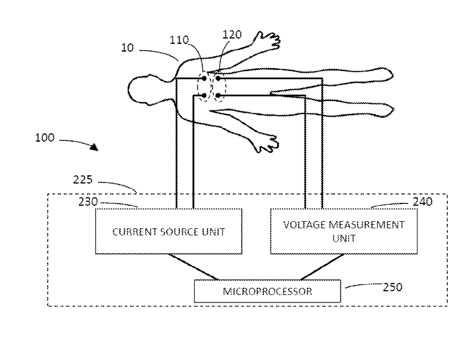
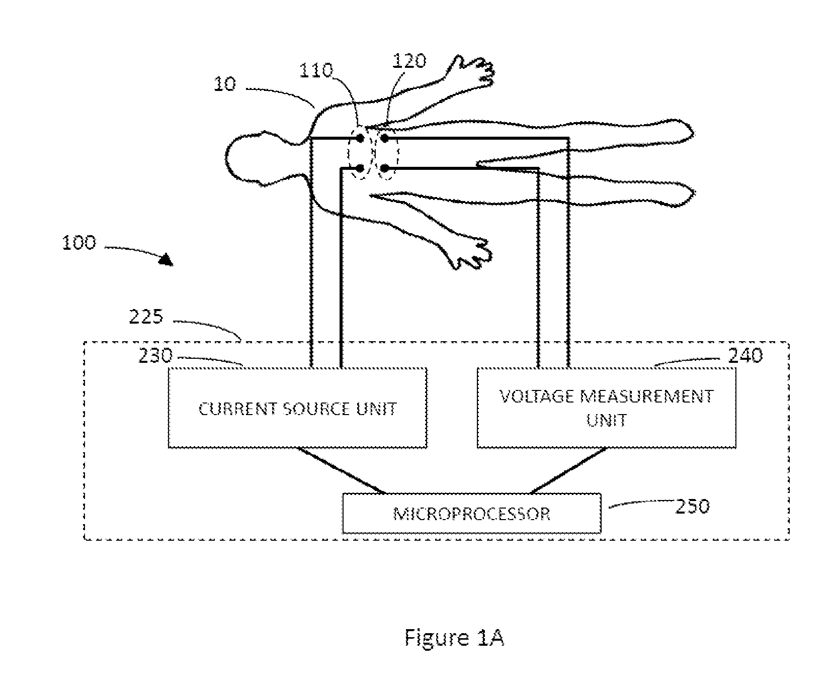
[0244]We simulated a portable bio-impedance system that consists of four electrodes. The system employs a parametric EIT algorithm to reconstruct the resistivity values of each lung from two impedance measurements. In each measurement, the voltage between the one electrode pair was measured while current was injected through a second pair of electrodes. A second order modified Newton-Raphson algorithm was used to calculate the optimal values for the two parameters, i.e., the resistivity of the two lungs. The reconstruction algorithm (i.e., the Newton-Raphson algorithm) was based on a predefined and known fixed thoracic geometry with a perimeter of ˜100 cm. For such a system to correctly measure and monitor lung edema in subjects of other thoracic sizes (i.e., a lung perimeter of less than 100 cm or greater than 100 cm), it is important to validate a calibration curve for adjusting the physical voltage measurements made on the various subjects to a calculated expected va...

example 2

[0259]With reference to FIGS. 11A-E, we connected four electrodes to a subject and conducted a continuous (fast sampling) bioimpedance monitoring for over 10 seconds. Two pairs of electrodes, an injecting pair and a measuring pair, were placed on the thorax. Each pair contained one electrode that was placed on the left side of the thorax and another electrode that was placed on the right side of the thorax. The voltage resulting from the injected current was monitored during a variety of non-tidal breathing modes: normal breathing (FIGS. 11A-B), deep breathing (FIG. 11C), no breathing (FIG. 11D) and deep inhalation followed by complete emptying of the lungs (FIG. 11E).

[0260]We found that the difference in breathing inhale / exhale voltage peaks is significant, ˜30%, confirming that the breathing artifact is a major source of noise. We also found that the heart cycle was not a significant source of noise.

[0261]In addition, we found that the variability of the voltage measured at differ...


PUM


Abstract

A method for measuring the impedance of a portion of a subject, by passing a known current provided by a current source unit between a first pair of electrodes contacting the skin surface of the subject. The measuring of a voltage with a voltage measuring instrument, between at least one second pair of electrodes contacting the skin surface of the subject when the current source unit is passing the known current through the first pair of electrodes; calculating the bio-impedance of the portion of the subject based on the known current and the calibrated voltage.

Description

FIELD OF THE INVENTION[0001]The present disclosure relates to the field of instrumentation, as well as related methods, for monitoring and evaluating biophysical measurements in the body. In particular, the disclosure relates to the measurement of electrical impedance on the body of a subject.BACKGROUND OF THE INVENTION[0002]Bioimpedance is the response of a living organism (or a portion thereof, such as a body part, organ, tissue, or the like) to an externally applied electric current. It is a measure of the opposition to the flow of that electric current through the tissues. The measurement of the bioimpedance (or bioelectrical impedance) has proved useful as a non-invasive method for measuring various parameters of the body.[0003]However, bioimpedance measurements are subject to many confounding factors that create challenges in maintaining accuracy, standardization and repeatability of measurements across subjects and across time.[0004]The voltage readout from a bioimpedance mea...

Claims


Application Information

Patent Timeline
Patent Type & Authority Applications(United States)
IPC IPC(8): A61B5/053A61B5/08A61B5/00G01R27/02
CPCA61B5/0537G01R27/02A61B5/0531A61B5/0535A61B5/4878A61B5/0536A61B5/0809A61B5/4869A61B5/318
Inventor DRORI, ORENARAD, SHIMONKRIEF, HAIM
Owner CARDIOLOGIC INNOVATIONS
Learn More