
Method and system with divided cannula having low oxygen flow rate and improved end-tidal co2 measurement

a divided cannula and oxygen flow rate technology, applied in the field of new and improved divided nasal cannulas, can solve the problems of skewing affecting the accuracy of analysis, and the amount of oxygen supplied to the patient did not equal the amount of oxygen, so as to facilitate communication, facilitate only supplying, and facilitate communication

Active Publication Date: 2014-09-18
SALTER LABS LLC
View PDF6 Cites 18 Cited by
  • Summary
  • Abstract
  • Description
  • Claims
  • Application Information

AI Technical Summary

Benefits of technology

This patent presents a new nasal cannula that improves the collection of a patient's breath gases for accurate detection of carbon dioxide levels. By dividing the nostril into two separate cavities, the cannula can provide more oxygen to the patient while assisting with exhalation and detecting carbon dioxide levels. This allows for a more accurate measurement of the patient's carbon dioxide levels, which can help with the diagnosis and treatment of medical conditions. Additionally, the cannula minimizes the flow of oxygen to the patient, ensuring an adequate amount is supplied while still maintaining the patient's bloodstream saturated with oxygen.

Problems solved by technology

While the prior art designs provide a significant improvement over the prior art, there still remain a number of issues that need to be addressed.
Specifically, it was discovered that with prior art cannulas, the amount of oxygen being supplied to the patient did not equal the amount of oxygen actually being absorbed into the bloodstream of the patient.
It was also found that administering more oxygen to the patient typically resulted in greater dilution of the end-tidal exhalation gases.
Such dilution adversely effects detection of the amount of end-tidal CO2 within the end-tidal exhalation gases of the patient thereby skewing the accurate analysis.

Method used


Image

  • Method and system with divided cannula having low oxygen flow rate and improved end-tidal co2 measurement
  • Method and system with divided cannula having low oxygen flow rate and improved end-tidal co2 measurement
  • Method and system with divided cannula having low oxygen flow rate and improved end-tidal co2 measurement

Examples


Embodiment Construction

[0022]The present invention will be understood by reference to the following detailed description, which should be read in conjunction with the appended drawings. It is to be appreciated that the following detailed description of various embodiments is by way of example only and is not meant to limit, in any way, the scope of the present invention.

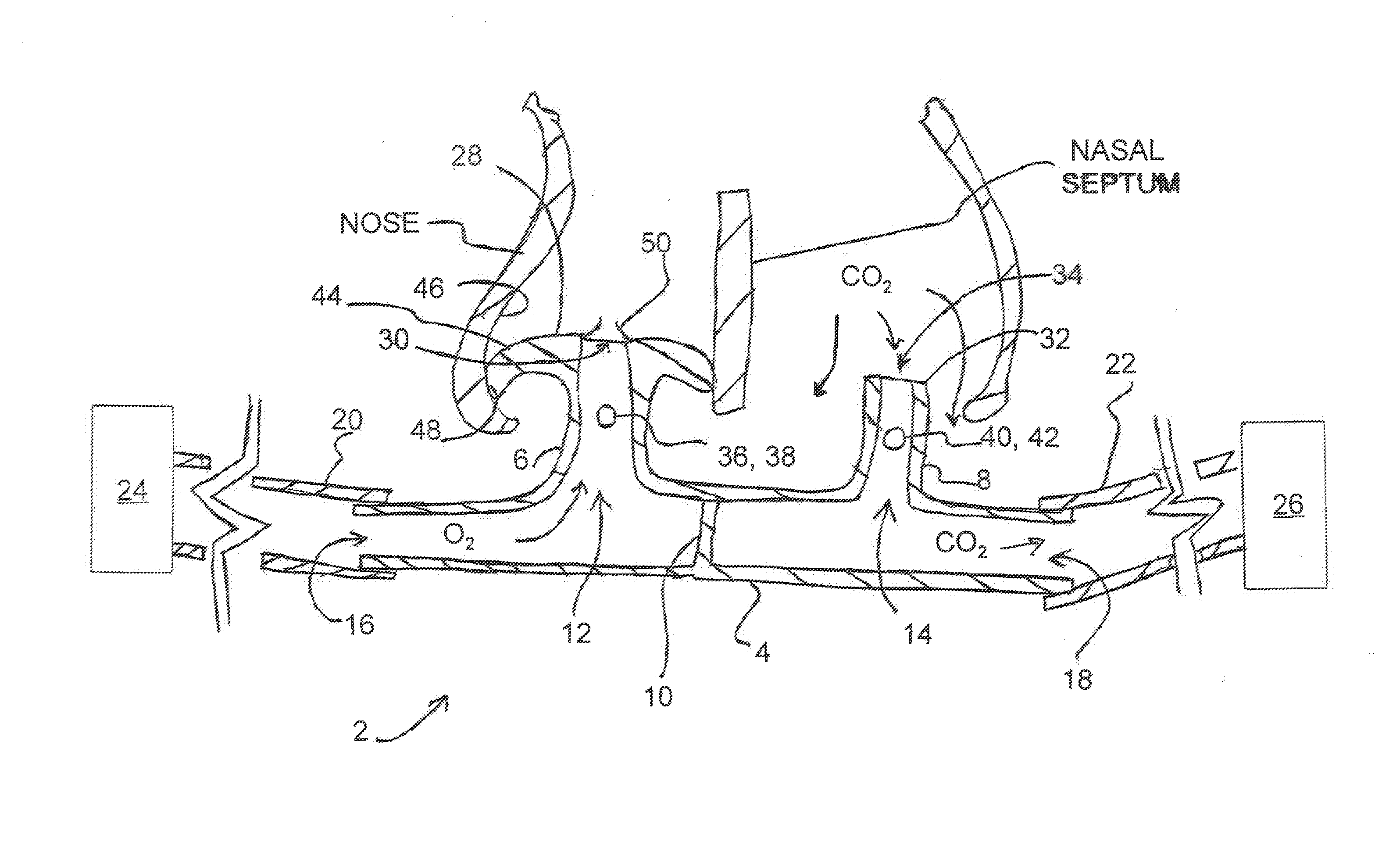
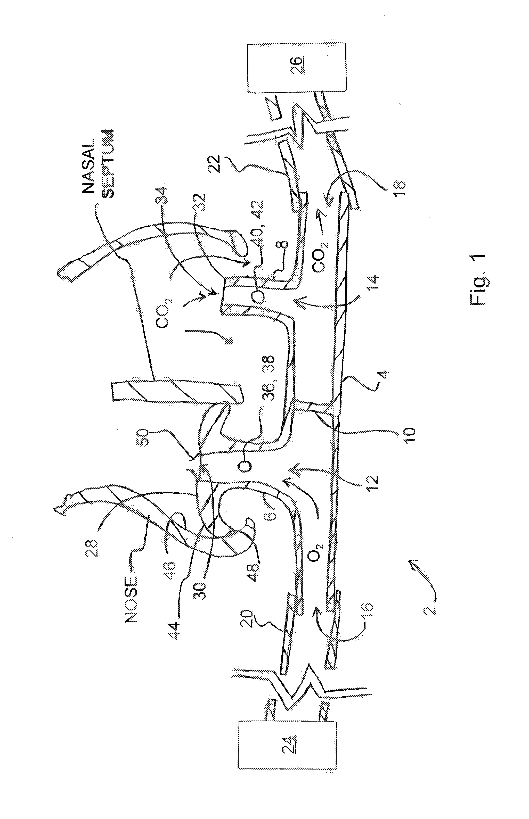
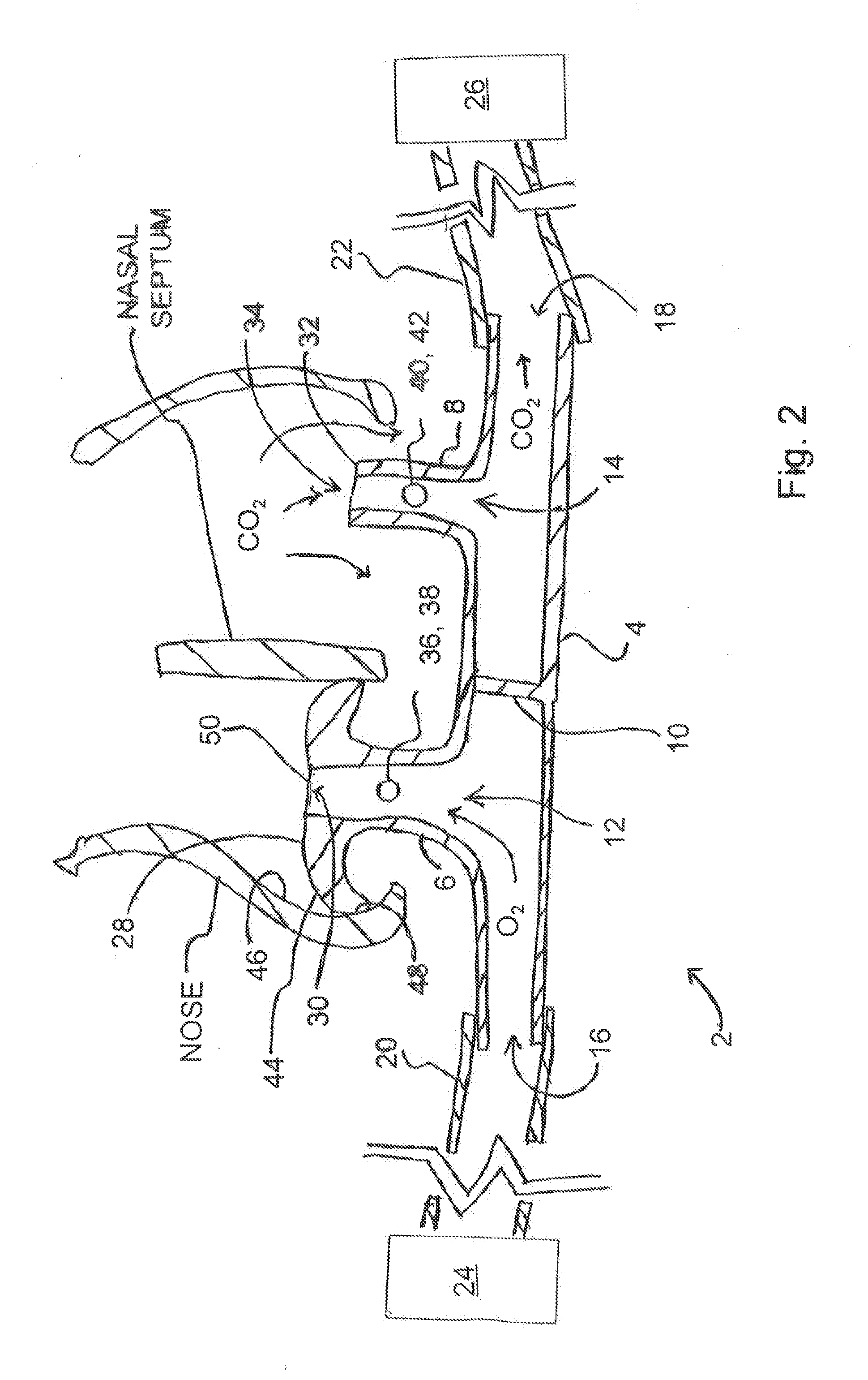
[0023]Turning now to FIGS. 1 and 2, a brief description concerning the various components of the present invention will now be briefly discussed. As can be seen in this embodiment, the nasal cannula 2 generally comprises a generally tubular elongate face piece 4 having a first insufflating nare 6 and a second sampling nare 8, respectively, and a dividing septum 10 located therebetween. The dividing septum 10 is disposed and generally centered within the face piece 4, between a pair of respective passages 12 and 14 which facilitate communication with the respective first and second nares 6 and 8.

[0024]A first opening 16 is formed in a first...


PUM


Abstract

A nasal cannula which comprises a face piece comprising first and second nares which each communicate with a respective nostril of a patient. A septum divides the face piece into first and second flow paths such that the first flow path communicates with the first nare and the second flow path communicates with the second nare. A leading end of the first nare is configured to form a fluid barrier within a first nostril and facilitate only supplying an insufflation gas, via the first flow path, to the patient and prevent exhausting any of exhaust gas, of the patient, through the first nostril of the patient. A leading end of the second nare is configured to facilitate collecting some of the exhaust gas, from the patient, via the second flow path as well as exhausting a remainder of the exhaust gas out through a second nostril of the patient.

Description

[0001]This application claims the benefit of U.S. provisional application Ser. No. 61 / 792,007 filed Mar. 15, 2013.FIELD OF THE INVENTION[0002]The present invention relates to a new and improved divided nasal cannula which permits improvement in the amount of oxygen which is actually dissolved within the bloodstream of the patient, at a lower oxygen supply flow rate to the patient, and also improves collection and measurement of a substantially undiluted sample of the end-tidal carbon dioxide contained within the exhaled gases from the patient.BACKGROUND OF THE INVENTION[0003]As is well known in the art, a number of divided cannulas are currently available on the market which assist with both supplying a desired treatment or insufflation gas, such as oxygen, to the patient via a first insufflating nare of the nasal cannula and also facilitates detection of a desired exhaled gas, such as carbon dioxide, via a second sampling nare of the nasal cannula. U.S. Pat. Nos. 5,335,656 and 6,65...

Claims


Application Information

Patent Timeline
IPC IPC(8): A61B5/097A61M16/00A61M16/20A61M16/06A61B5/083
CPCA61B5/097A61M16/0677A61M16/0057A61M16/208A61B5/0836A61M16/0672A61M16/085A61M2202/0208A61M2230/432
Inventor CHUA, JAMES
Owner SALTER LABS LLC
Learn More