
Intraocular lens inserters

a technology of inserters and inserters, which is applied in the field of inserters of intraocular lenses, can solve the problems of more difficult control of energy storage devices, more difficulty for surgeons to hold devices in the desired orientation and position, etc., and achieve the effect of reducing manual for

Active Publication Date: 2014-09-18
ALCON INC
View PDF33 Cites 42 Cited by
  • Summary
  • Abstract
  • Description
  • Claims
  • Application Information

AI Technical Summary

Benefits of technology

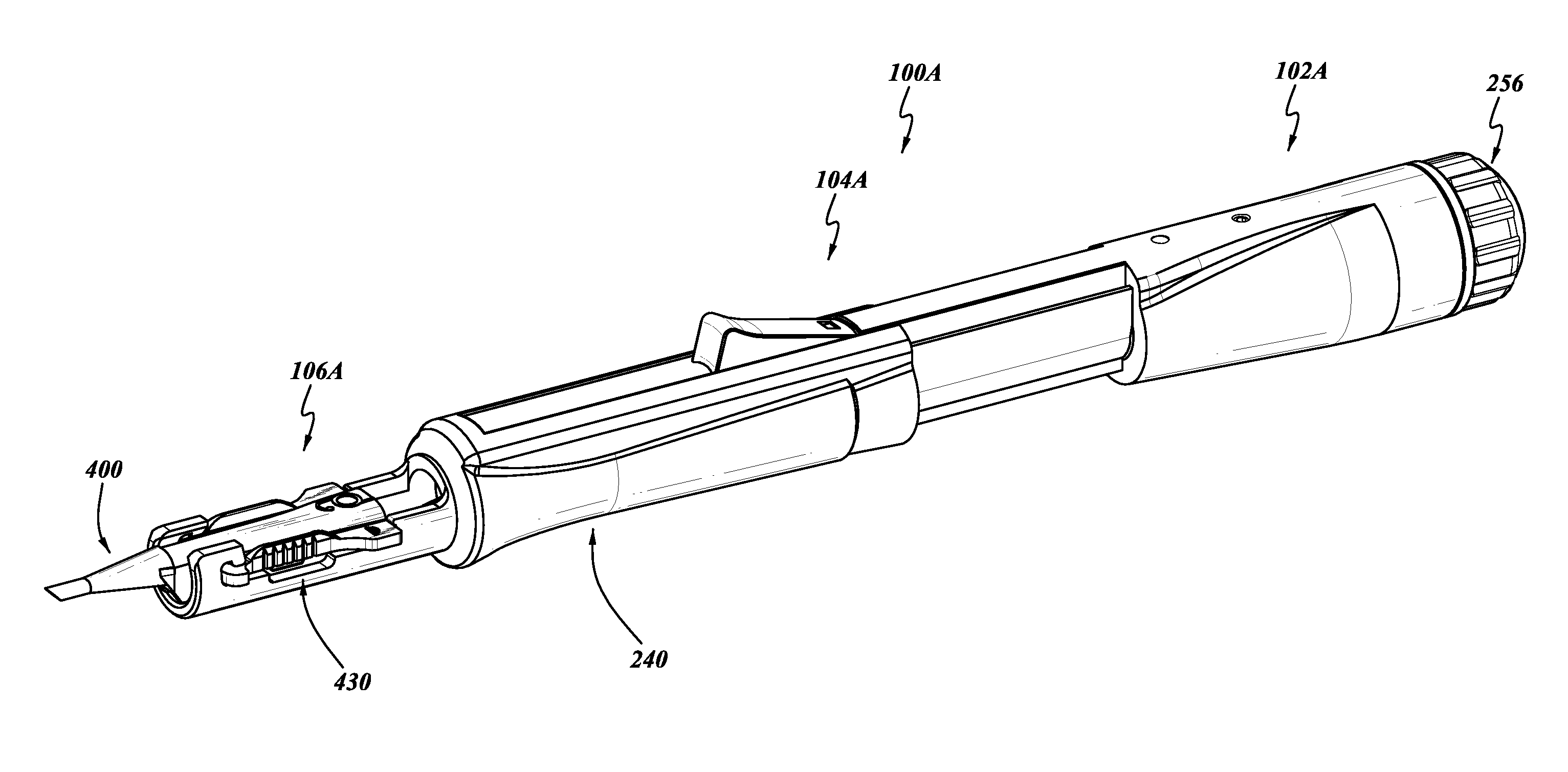
The invention provides an intraocular lens inserter design that allows a surgeon to actuate and discharge a lens with one hand, reducing the manual force required. It also reduces the cost of the device by using an energy storage device and an actuating circuit operating with a compressible fluid that allows for more fine control over the velocity of downstream components. Additionally, the intraocular lens inserter can be made with an incorporated energy storage device and a movement control actuator, which results in a single-use device that can be disposable, thereby avoiding costs associated with resterilization and potential cross-contamination.

Problems solved by technology

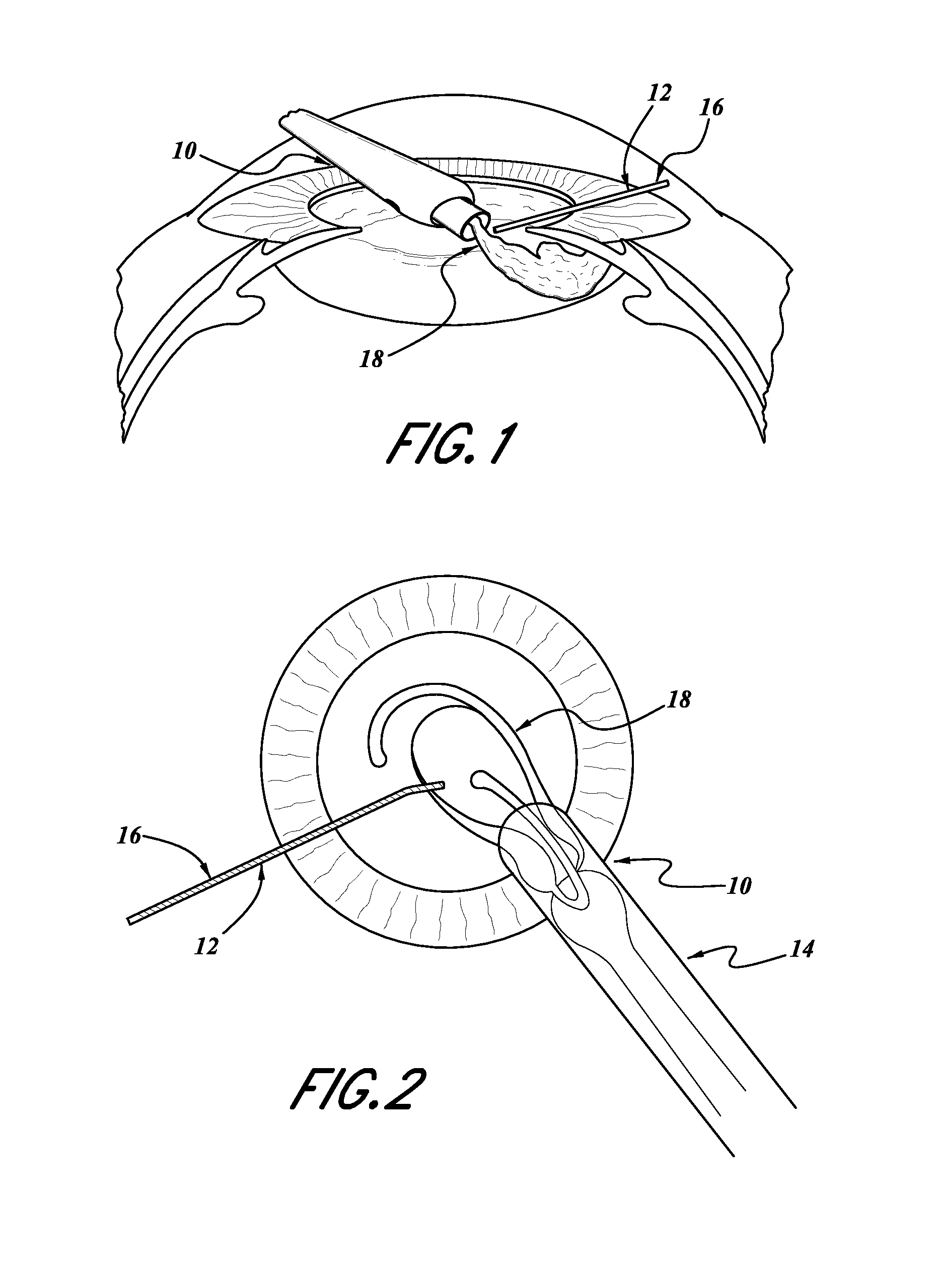
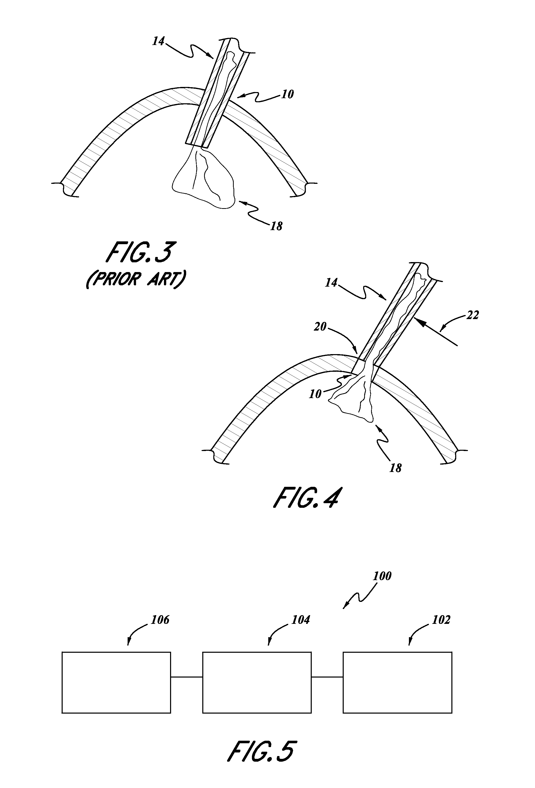
This makes it more difficult for the surgeon to hold the device in the desired orientation and location during insertion.
This problem is more significant in the surgical procedures more recently adopted such as that described above with reference to FIG. 4.
However, such energy storage devices are more difficult to control for providing, for example, constant velocity output.

Method used


Image

  • Intraocular lens inserters
  • Intraocular lens inserters
  • Intraocular lens inserters

Examples


Embodiment Construction

[0057]The following detailed description is merely illustrative in nature and is not intended to limit the embodiments of the subject matter or the application and uses of such embodiments. As used herein, the word “exemplary” means “serving as an example, instance, or illustration.” Any implementation described herein as exemplary is not necessarily to be construed as preferred or advantageous over other implementations. Furthermore, there is no intention to be bound by any expressed or implied theory presented in the proceeding technical field, background, brief summary, or the following detailed description.

[0058]Certain terminology may be used in the following description for the purpose of reference only, and thus are not intended to be limiting. For example, terms such as “upper”, “lower”, “above”, and “below” refer to directions in the drawings to which reference is made. Terms such as “proximal”, “distal”, “front”, “back”, “rear”, and “side” describe the orientation and / or l...


PUM


Abstract

An intraocular lens inserter can include an energy storage portion, an actuator portion, and a lens support portion. The energy storage portion can include a compressible energy storage device, such as a compressible fluid, springs, and other devices. The inserter can include an actuator portion operating with a substantially incompressible fluid, such as liquids or other noncompressible fluids. The actuator can be configured to provide an operator with control over the release of energy from the energy storage portion so as to move a plunger for the discharge of a lens from an intraocular lens cartridge.

Description

RELATED APPLICATIONS[0001]Any and all applications for which a foreign or domestic priority claim is identified in the Application Data Sheet as filed with the present application are hereby incorporated by reference under 37 CFR 1.57.[0002]The present application is a continuation of International Application No. PCT / US2013 / 044183 filed Jun. 4, 2013, titled INTRAOCULAR LENS INSERTER and published as WO 2013 / 0184727, which claims priority to U.S. Provisional Patent Application No. 61 / 655,255 filed Jun. 4, 2012, the entire contents of both of which are hereby incorporated by reference.TECHNICAL FIELD[0003]The inventions disclosed herein generally relate to devices and methods for inserting intraocular lens into an eye of an animal.BACKGROUND[0004]A cataract is a clouding that develops in the crystalline lens of the eye or in its envelope (lens capsule), varying in degree from slight to complete opacity and obstructing the passage of light. Early in the development of age-related cata...

Claims


Application Information

Patent Timeline
Patent Type & Authority Applications(United States)
IPC IPC(8): A61F2/16
CPCA61F2/167A61F2/1678A61F9/007A61F9/00736A61F2/1662
Inventor AULD, JACK R.
Owner ALCON INC
Learn More