
Flexbeam to Rotor Blade Interface

Active Publication Date: 2014-09-25
SIKORSKY AIRCRAFT
View PDF1 Cites 8 Cited by
  • Summary
  • Abstract
  • Description
  • Claims
  • Application Information

AI Technical Summary

Benefits of technology

This patent offers a spar for a rotor blade assembly, which includes a hollow tubular body with a spacer protruding from one of its surfaces. The invention also includes a hole in the spar that matches with a hole in an adjacent flexbeam assembly. This spar is designed to create a match fit with the flexbeam assembly, ensuring a secure connection. Additionally, a clamp with a first through hole is used to attach the spar to the flexbeam, a fastener assembly is installed to further strengthen the connection, and a portion of the spacer is removed for a better fit. Overall, this spar design improves the performance and efficiency of the rotor blade assembly.

Problems solved by technology

This type of tooling and the process used to manufacture a spar is complex and intolerant of redesign or development changes to improve the ease of assembling the spar and flexbeam.
Generally such changes require large technical and financial investments, as well as a large amount of time.

Method used


Image

  • Flexbeam to Rotor Blade Interface
  • Flexbeam to Rotor Blade Interface
  • Flexbeam to Rotor Blade Interface

Examples


Embodiment Construction

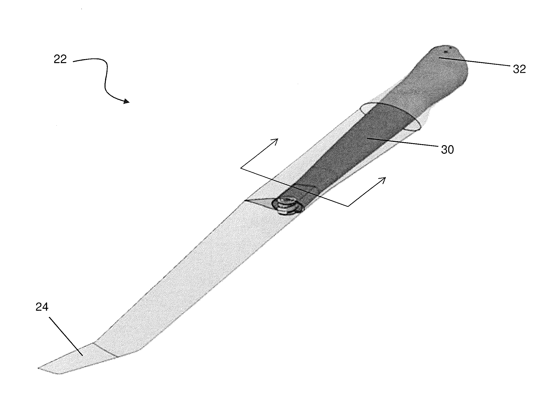
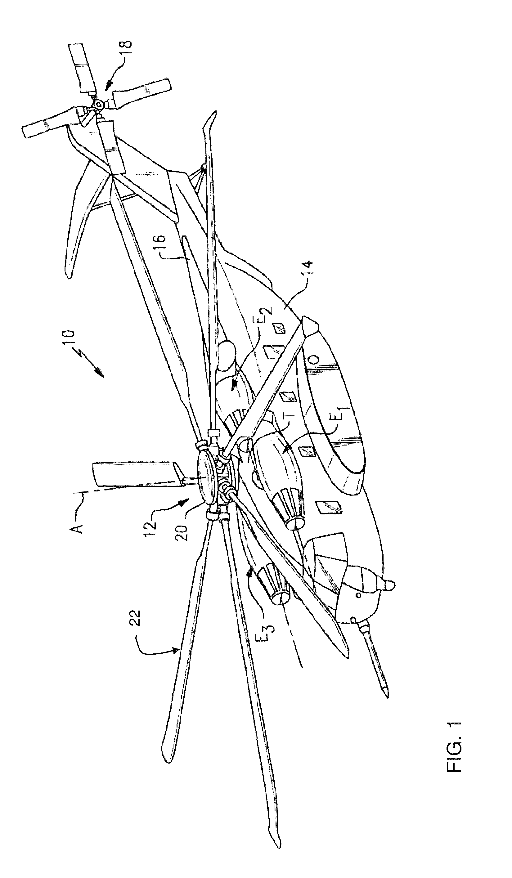
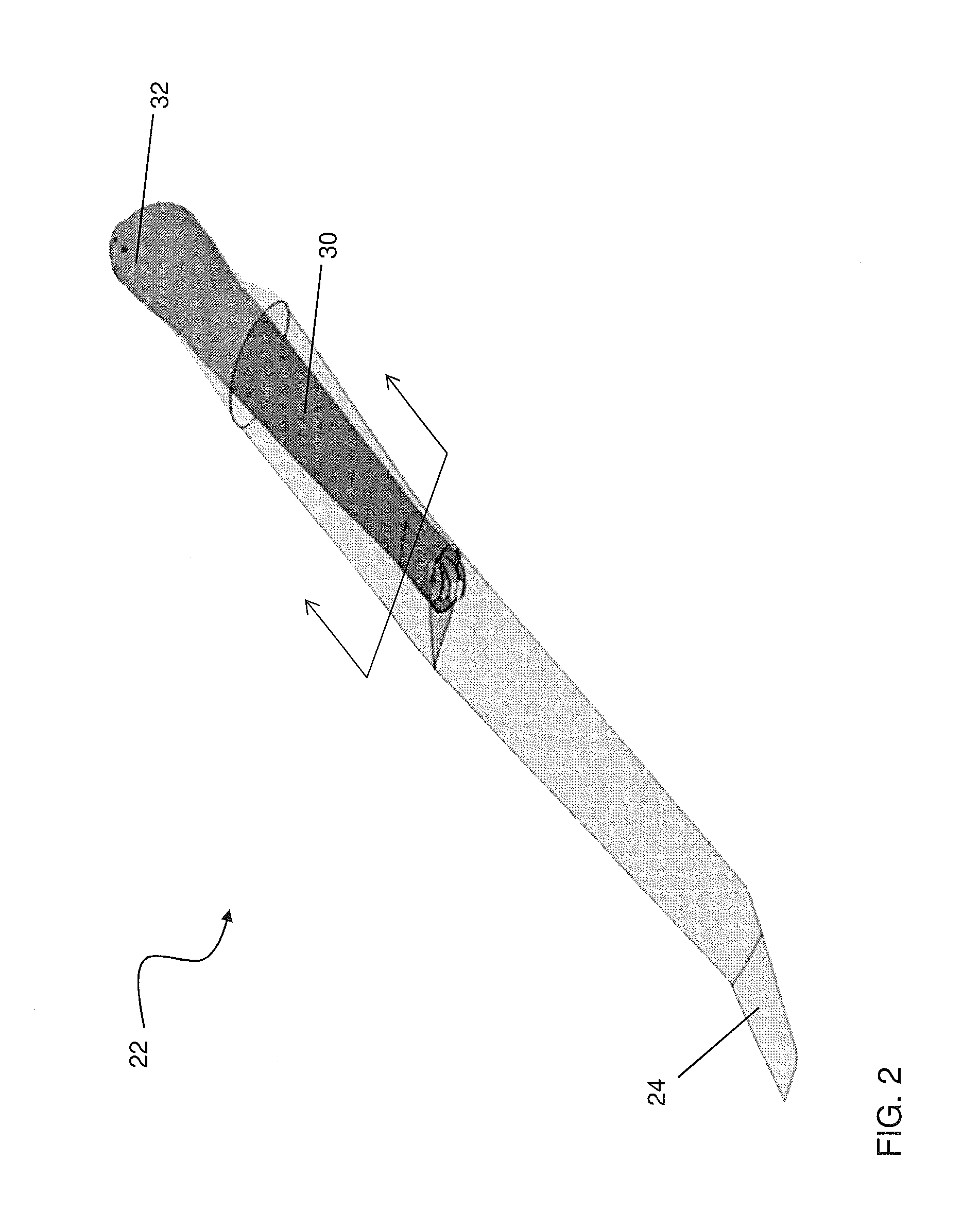
[0016]FIG. 1 schematically illustrates a rotary-wing aircraft 10 having a main rotor system 12. The aircraft 10 includes an airframe 14 having an extending tail 16 which mounts a tail rotor system 18 as an anti-torque system. The main rotor assembly 12 is driven about an axis of rotation A through a main gearbox (illustrated schematically at T) by one or more engines E. The main rotor system 12 includes a rotor hub 20 having a plurality of rotor blade assemblies 22 mounted to and projecting radially outwardly therefrom. Although a particular helicopter configuration is illustrated and described in the disclosed non-limiting embodiment, other configurations and / or machines, such as high speed compound rotary wing aircraft with supplemental translational thrust systems, dual contra-rotating coaxial rotor system aircraft, turboprops, tilt-rotors, and tilt-wing aircraft, will also benefit from the present invention.

[0017]Referring now to the exemplary rotor blade assembly 22 illustrated...


PUM

PropertyMeasurementUnit
Lengthaaaaaaaaaa

Abstract

A spar for a rotor blade assembly is provided including a generally hollow tubular body. A spacer protrudes from at least one surface of the body along a length of the body. A hole extends through the body and the spacer. The hole is configured to align with a through hole in an adjacent flexbeam assembly. The spacer is configured to contact a surface of the adjacent flexbeam assembly to create a match fit between the body and the flexbeam assembly.

Description

BACKGROUND OF THE INVENTION[0001]This invention relates to a rotor system of a rotary wing aircraft and, more particularly, to a rotor blade assembly for a rotary wing aircraft.[0002]Conventional rotary wing aircrafts, such as helicopters for example, include a rotor hub configured to rotate about an axis and having multiple rotor blade assemblies mounted thereto. Each rotor blade assembly includes a flexbeam extending outwardly from the rotor hub through the hollow center of a spar or torque tube. The spar is coupled to an outboard end of the flexbeam such that rotation of the rotor hub is transmitted to the spar. The interface between the flexbeam and the spar often requires installation of a plurality of shims and assembly of separate upper and lower spar components. In applications where the interface between the flexbeam and the spar is not near either end of the spar, the installation of shims and other components may be imprecise.[0003]In addition, hard tooling is used to for...

Claims


Application Information

Patent Timeline
IPC IPC(8): B64C27/33
CPCB64C27/33B64C27/473B64C27/48Y10T29/49332
Inventor THOMAS, JUSTINNUSSENBLATT, ERIC LUCIENPARSONS, ERIC S.CASEY, RYAN THOMASHUNTER, DAVID H.
Owner SIKORSKY AIRCRAFT
Learn More