
Closed-loop vagus nerve stimulation
a vagus nerve and closed-loop technology, applied in the field of neurodegenerative diseases, can solve the problems of moderate efficacy, procedures suffer from a number of fundamental limitations, and can not be used in the field of closed-loop vagus nerve stimulation, so as to reduce the time and number of interactions, enhance the manual selection of the optimum treatment magnitude, and optimize the energy utilization
- Summary
- Abstract
- Description
- Claims
- Application Information
AI Technical Summary
Benefits of technology
Problems solved by technology
Method used
Image

Examples
Embodiment Construction
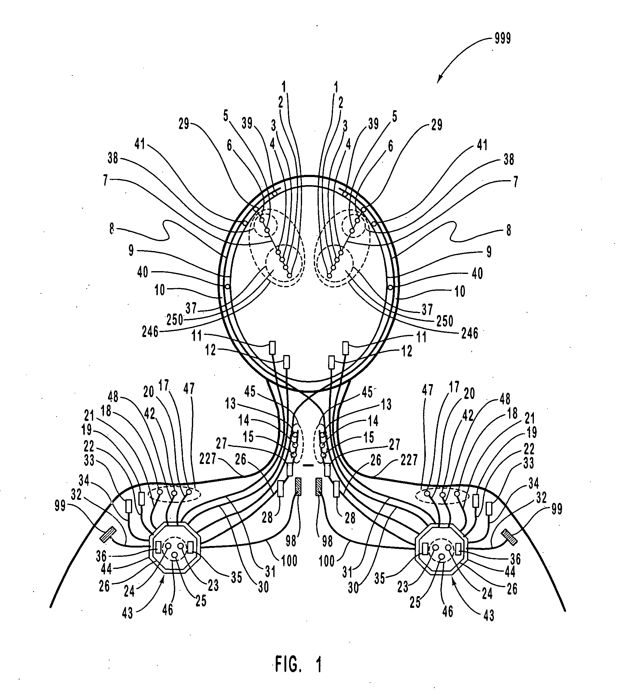
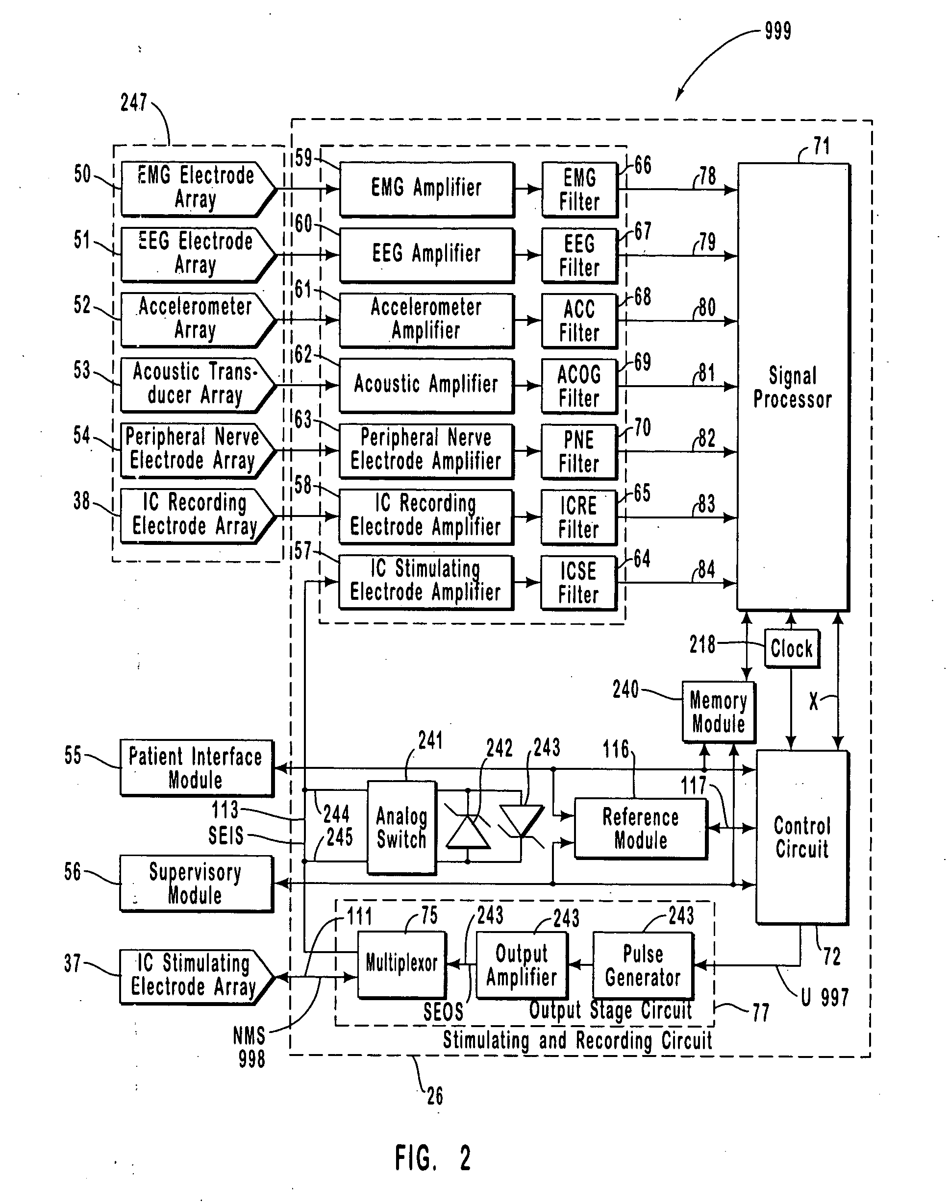
[0107]FIG. 1 is a schematic diagram of one embodiment of the intracranial stimulator of the present invention implanted bilaterally in a human patient. In the embodiment illustrated in FIG. 1, two neurological control systems 999 are shown implanted bilaterally. Each system 999 includes a stimulating and recording unit 26 and one or more intracranial components described below. As described in this illustrative embodiment, the intracranial components preferably include a stimulating electrode array 37. However, it should become apparent to those of ordinary skill in the relevant art after reading the present disclosure that the stimulating electrodes may also be extracranial; that is, attached to a peripheral nerve in addition to or in place of being located within the cranium. As shown in FIG. 1, stimulating and recording unit 26 of each neurological control system 999 is preferably implanted contralateral to the intracranial components of the device.
[0108]As one skilled in the rel...
PUM
 Abstract
Description
Claims
Application Information