Sealed crimp connection methods

Active Publication Date: 2011-04-14
APTIV TECH LTD
View PDF2 Cites 42 Cited by
  • Summary
  • Abstract
  • Description
  • Claims
  • Application Information

AI Technical Summary

Benefits of technology

[0006]One aspect of the invention is improving the protection at the terminal/wire conductor connection

Problems solved by technology

Conventional thinking in the wiring arts is that a dielectric, insulating seal material added to a crimp connection may yield

Method used


Image

  • Sealed crimp connection methods
  • Sealed crimp connection methods
  • Sealed crimp connection methods

Examples


Embodiment Construction

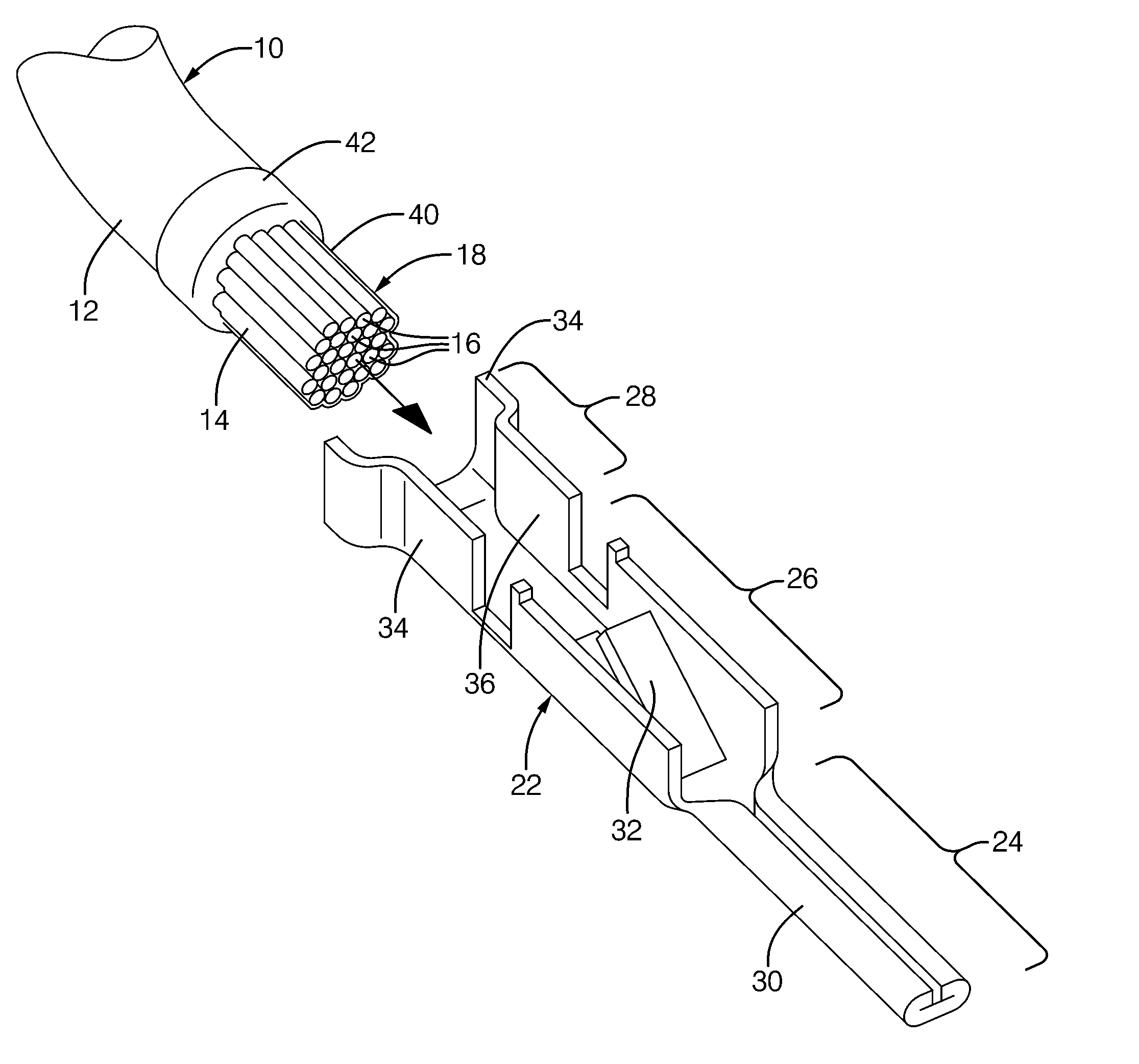
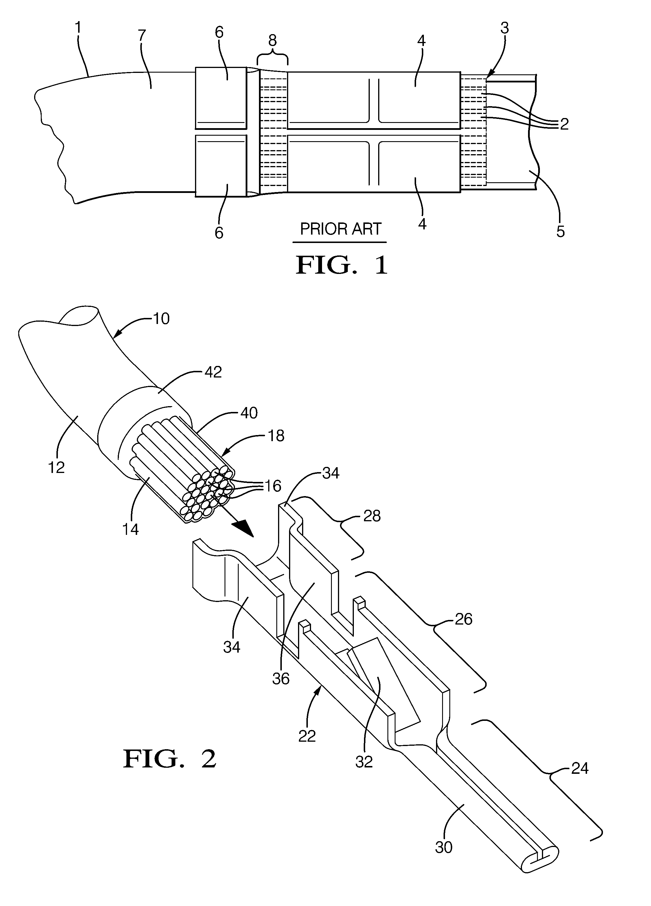
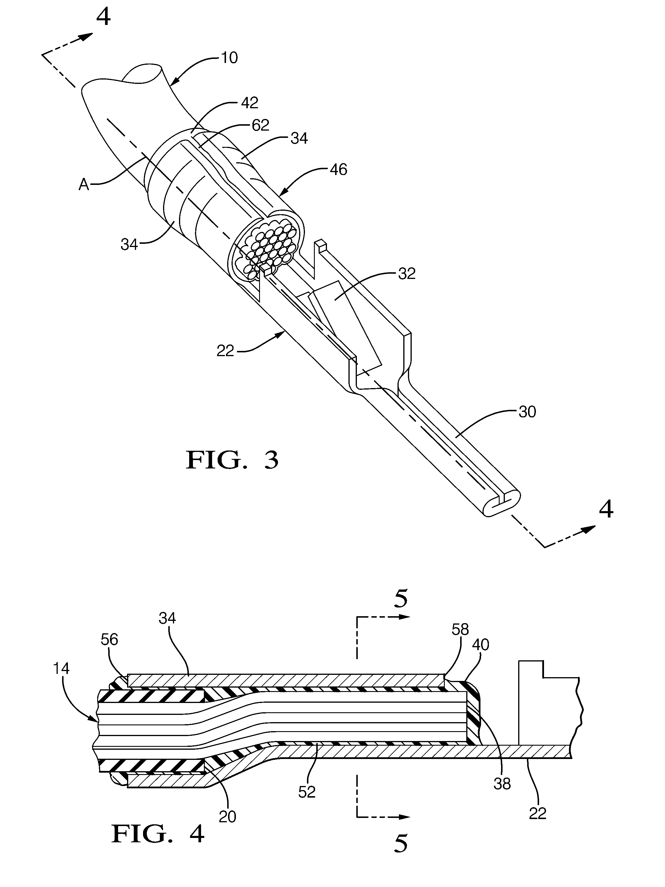
[0021]Referring to FIG. 2-6, a cable, or wire conductor 10 is disposed along a longitudinal axis A. Wire conductor 10 has an insulative outer cover 12 and an aluminum-based inner core 14. The term “aluminum based” as used in this document herein is defined to mean pure aluminum or an aluminum alloy where aluminum is the main metal in the alloy. Cover 12 surrounds inner core 14. Inner core 14 is constructed of a plurality of individual wire strands 16 that are bundled and twisted together. Wire strands 16 are useful to provide flexation of conductor 10 when conductor 10 is installed in a wiring application (not shown), such as during the manufacture of a vehicle. Alternately, the inner core of the wire conductor may be a single wire strand. An end portion (not shown) of cover 12 of conductor 10 is removed to expose a portion of inner core 14. Exposed portion of inner core 14 is a lead 18 of wire conductor 10. Lead 18 extends from an axial edge 20 of cover 12.

[0022]A copper-based term...


PUM

PropertyMeasurementUnit
Timeaaaaaaaaaa
Forceaaaaaaaaaa
Pressureaaaaaaaaaa

Abstract

Methods of making a sealed crimp connection attaching a terminal to a wire conductor are provided. A layer of fluid conformal coating is applied to overlie a terminal and underlie at least a lead of the wire conductor upon at least the lead being received into the terminal. The terminal, the fluid layer, and at least the lead of the wire conductor are crimped to form the crimp connection. Fluid conformal coating is displaced where an abutting surface of the terminal makes contact with at least the lead of the wire conductor. The fluid conformal coating is cured to a non-fluid state. The fluid conformal coating may be formed of an acrylated urethane material that may provide an increased pull force and a low crimp resistance in the crimp connection. The crimp connection may be constructed using a manufacturing process on an automated assembly line.

Description

CROSS-REFERENCE TO CLAIM OF PRIORITY[0001]This application is a continuation-in-part of U.S. application Ser. No. 12 / 582,158 filed 20 Oct. 2009, which is a continuation-in-part of U.S. application Ser. No. 12 / 575,689 filed on 8 Oct. 2009, which claims priority to U.S. Provisional Application U.S. Ser. No. 61 / 243,650.TECHNICAL FIELD[0002]The invention relates to a connection between a terminal and a wire conductor.BACKGROUND OF INVENTION[0003]Referring to FIG. 1, it is known to apply a sealant to a lead of the wire conductor (1) having wire strands (2) and crimp the sealed lead (3) to the core wings (4) of a terminal (5) and attach the terminal (5) to the wire conductor (1) that affords protection against contaminants that may negatively affect the electrical and mechanical operating performance therein. The insulator wings (6) of the terminal (5) are crimped to the insulative cover (7) of the wire conductor (1) and are spaced apart from the core wings (4) crimped to the sealed lead ...

Claims


Application Information

Patent Timeline
IPC IPC(8): H01R43/04
CPCH01R4/184H01R4/185H01R4/62H01R4/70Y10T29/49185H01R43/048Y10T29/49174Y10T29/49176Y10T29/49171H01R13/5216H01R4/04H01R43/00
Inventor MARTAUZ, FRANCIS D.SEIFERT, KURT P.
Owner APTIV TECH LTD
Why Eureka
Try Eureka