Computer-aided die design apparatus

Inactive Publication Date: 2014-09-25
HONDA MOTOR CO LTD
View PDF1 Cites 2 Cited by
  • Summary
  • Abstract
  • Description
  • Claims
  • Application Information

AI Technical Summary

Benefits of technology

The technology described in this patent improves the accuracy of calculating the speed at which a resin becomes compressed. However, it assumes that the process is complete and stops analyzing the resin flow when the speed becomes zero. This can be inaccurate, as there may be some residual flow of the resin. The invention improves accuracy by accurately determining when the die-clamping is complete. This results in a more accurate analysis of the resin flow behavior.

Problems solved by technology

The configuration of the technology described in Reference improves the calculation accuracy of the compression speed, but it assumes that die-clamping is finished and terminates the analysis immediately after the compression speed becomes zero, so that it still has a drawback in the point of insufficient accuracy of the resin flow behavior analysis.

Method used


Image

  • Computer-aided die design apparatus
  • Computer-aided die design apparatus
  • Computer-aided die design apparatus

Examples


first embodiment

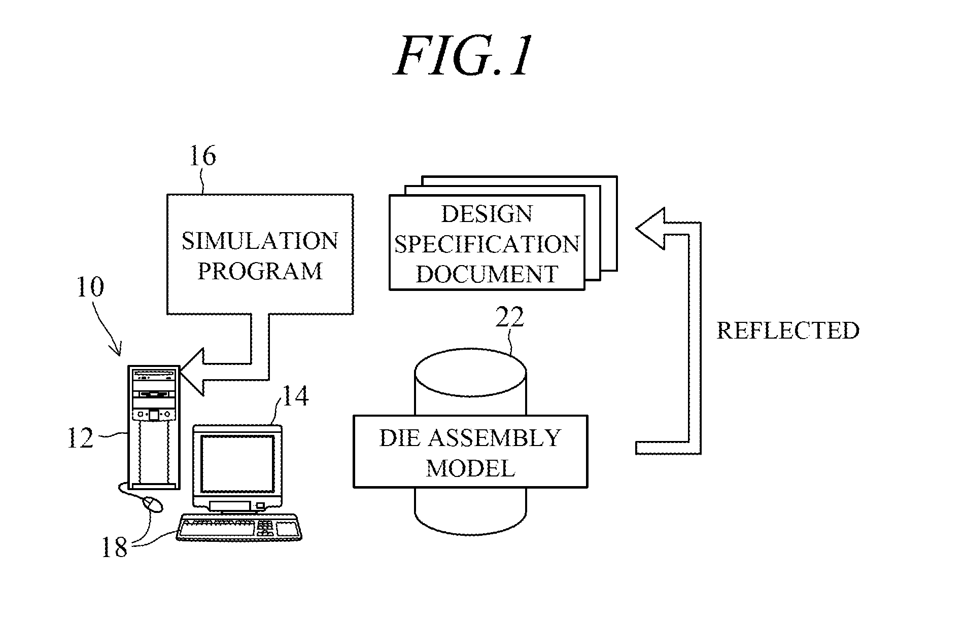
[0016]FIG. 1 is an overall schematic view of a computer-aided die design apparatus according to this invention.

[0017]Reference symbol 10 in FIG. 1 designates the apparatus, and the apparatus 10 comprises a computer 12, a display 14 connected to the computer 12, an interactive simulation program (sumulator) 16 loaded in the computer 12 that analyzes and displays on the display 14 resin flow behavior when resin charged into a die cavity is die-clamped by a press at a compression force F, and input devices 18 such as a keyboard, mouse and the like.

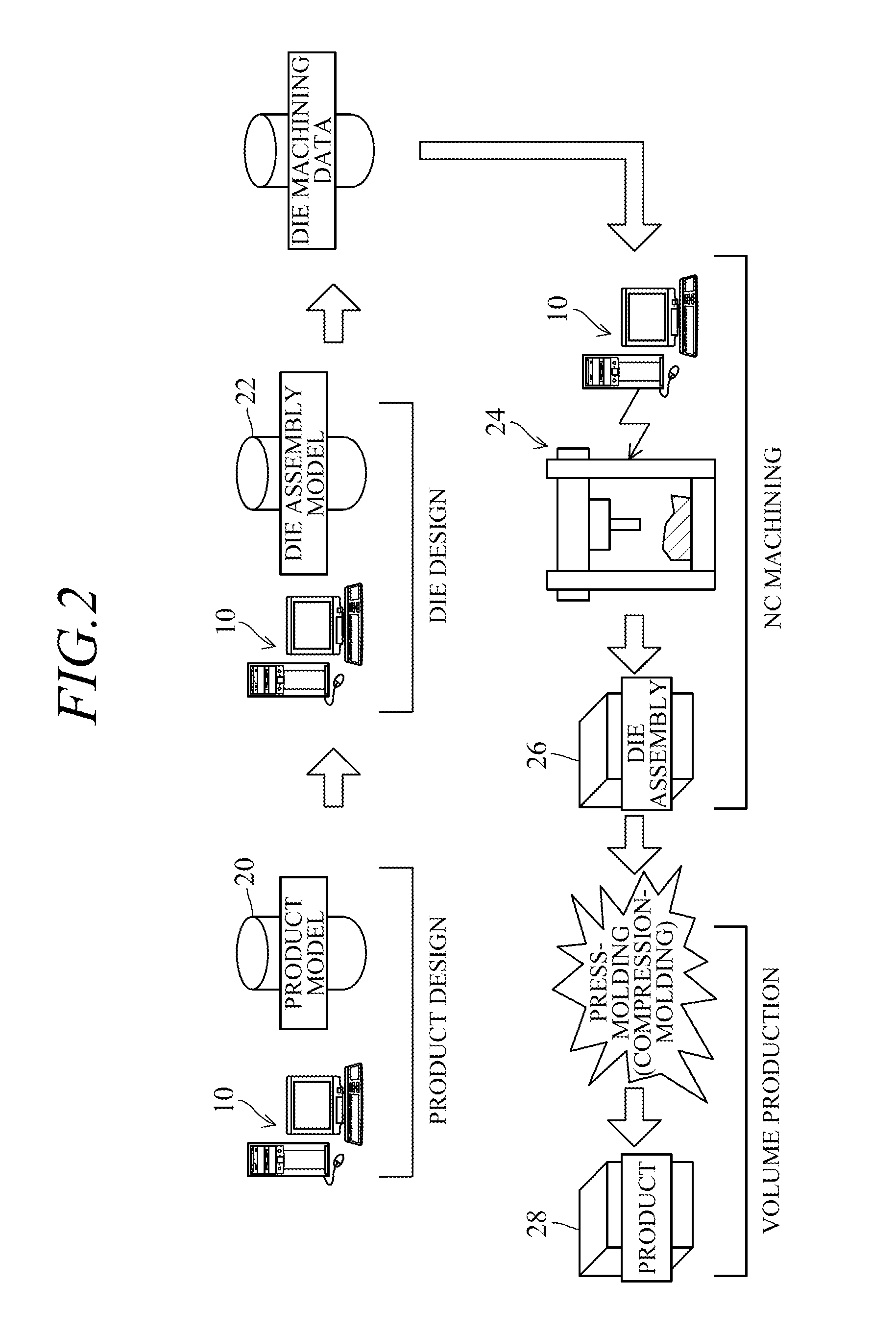
[0018]Thus, the apparatus 10 is configured as a die design apparatus utilizing CAE (Computer Aided Engineering), CAD (Computer Aided Design) / CAM (Computer Aided Manufacturing), or CIM (Computer Integrated Manufacturing).

[0019]In concrete terms, die design is performed as one part of a series of processes extending from product design to volume production, wherein a design engineer uses the input devices 18 to input data into the computer 12 i...

second embodiment

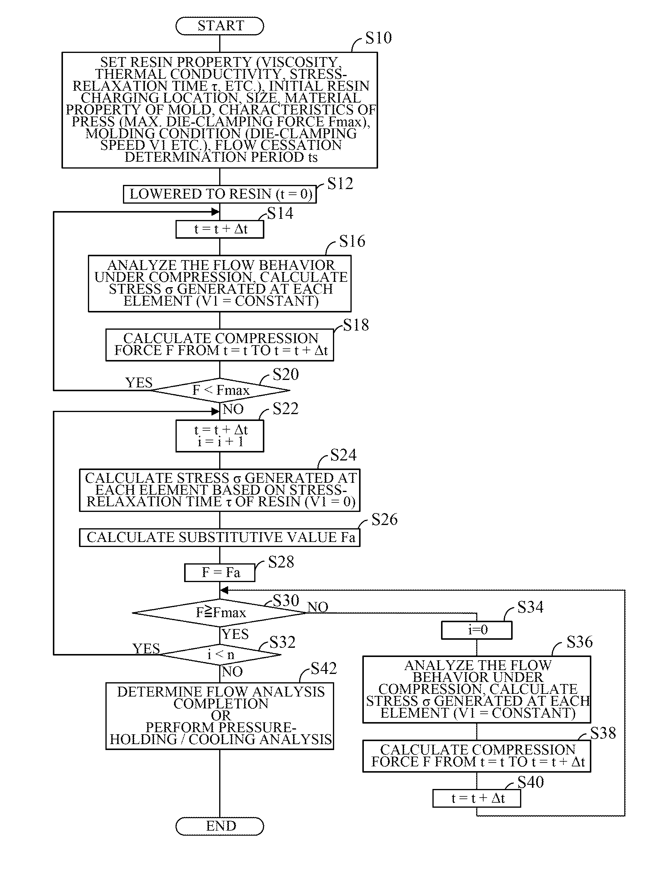
[0059]FIG. 6 is a flowchart, similar to that of FIG. 4, showing operations of the simulation program 16 of a computer-aided die design apparatus according to this invention.

[0060]Processing steps that are common between the flowchart of FIG. 6 and the flowchart of FIG. 4 are not explained in detail and the following explanation is focused on the points of difference from the first embodiment.

[0061]The first embodiment is configured so that in the processing according to the flowchart of FIG. 4, the upper limit value Fmax is set at a fixed value (maximum die-clamping force) determined from the properties of the press, and the die-clamping speed of the upper die 22a is controlled to V1 until the compression force F reaches the upper limit value Fmax.

[0062]In contrast to this, the second embodiment is configured to set the upper limit value at an arbitrary value (set compression force) Fs equal to or less than the maximum die-clamping force determined from the properties of the press.

[...


PUM


Abstract

In a computer-aided die design apparatus having a computer, a display adapted to be connected to the computer, and a simulator adapted to be loaded in the computer to analyze and display on the display flow behavior of resin when the resin charged into a die cavity is die-clamped by a press at a compression force, the simulator comprises an analyzer that analyzes the resin flow behavior by increasing the compression force for die-clamping the resin at a predetermined time interval until the increased compression force reaches an upper limit value, and a substitutive value calculator that calculates a substitutive value of the compression force based on a stress-relaxation time of the resin when the compression force has reached the upper limit value.

Description

TECHNICAL FIELD[0001]Embodiments of this invention relate to a die design apparatus using computer-aided engineering.RELATED ART[0002]A known technology concerning a computer-aided die design apparatus is described, for example, in Reference (Japanese Laid-Open Patent Application No. Hei 9(1997)-76267). This technology is configured to simulate the flow behavior of a flowable resin during molding by a press molding process.[0003]More specifically, the technology described in Reference is configured to successively calculate the compression speed (die-clamping speed) received by a resin based on hydraulic circuit characteristics, press-device-side elasticity and resin-side apparent elasticity, and analyze the resin flow behavior based on the calculated compression speed. In other words, the technology described in Reference is configured to avoid the inconvenience of the error that has conventionally arisen in the analysis owing to the compression speed being considered constant and ...

Claims


Application Information

Patent Timeline
IPC IPC(8): G06F17/50
CPCG06F17/5009G06F30/23G06F30/20
Inventor KOBAYASHI, MASATOSHIYAMASHITA, DAIYAYAMAGUCHI, YOSHIFUMI
Owner HONDA MOTOR CO LTD
Why Eureka
Try Eureka