Snap connection for two tubes

a technology of two tubes and clamps, applied in the direction of hose connections, pipe joints, other medical devices, etc., can solve problems such as problems presented in coupling tube assemblies, and achieve the effect of reducing fluid leakag

Inactive Publication Date: 2014-10-02
TYCO HEALTHCARE GRP LP
View PDF18 Cites 19 Cited by
  • Summary
  • Abstract
  • Description
  • Claims
  • Application Information

AI Technical Summary

Benefits of technology

[0010]According to another aspect of the present disclosure, the second tube portion defines an interior chamfer. In another aspect of the present disclosure, the interior chamfer is oriented at an oblique angle with respect to the longitudinal axis. The interior chamfer may be configured to slidably urge the protrusion of the coupling member in a radially inward direction. According to another aspect of the present disclosure, the medical tube assembly may further include a sealing member. The sealing member is configured to minimize fluid leakage between the first tube portion and the second tube portion.

Problems solved by technology

Challenges may be presented in coupling tube assemblies in urgent situations, given the challenges in maintaining a substantially fluid-tight seal between separable components.

Method used


Image

  • Snap connection for two tubes
  • Snap connection for two tubes
  • Snap connection for two tubes

Examples


Embodiment Construction

[0025]Embodiments of the presently disclosed medical tube assembly are described in detail with reference to the drawings, in which like reference numerals designate identical or corresponding elements in each of the several views. As used herein the term “distal” refers to that portion of the medical tube assembly, or component thereof, that is farther from the operator, while the term “proximal” refers to that portion of the medical tube assembly, or component thereof, that is closer to the operator.

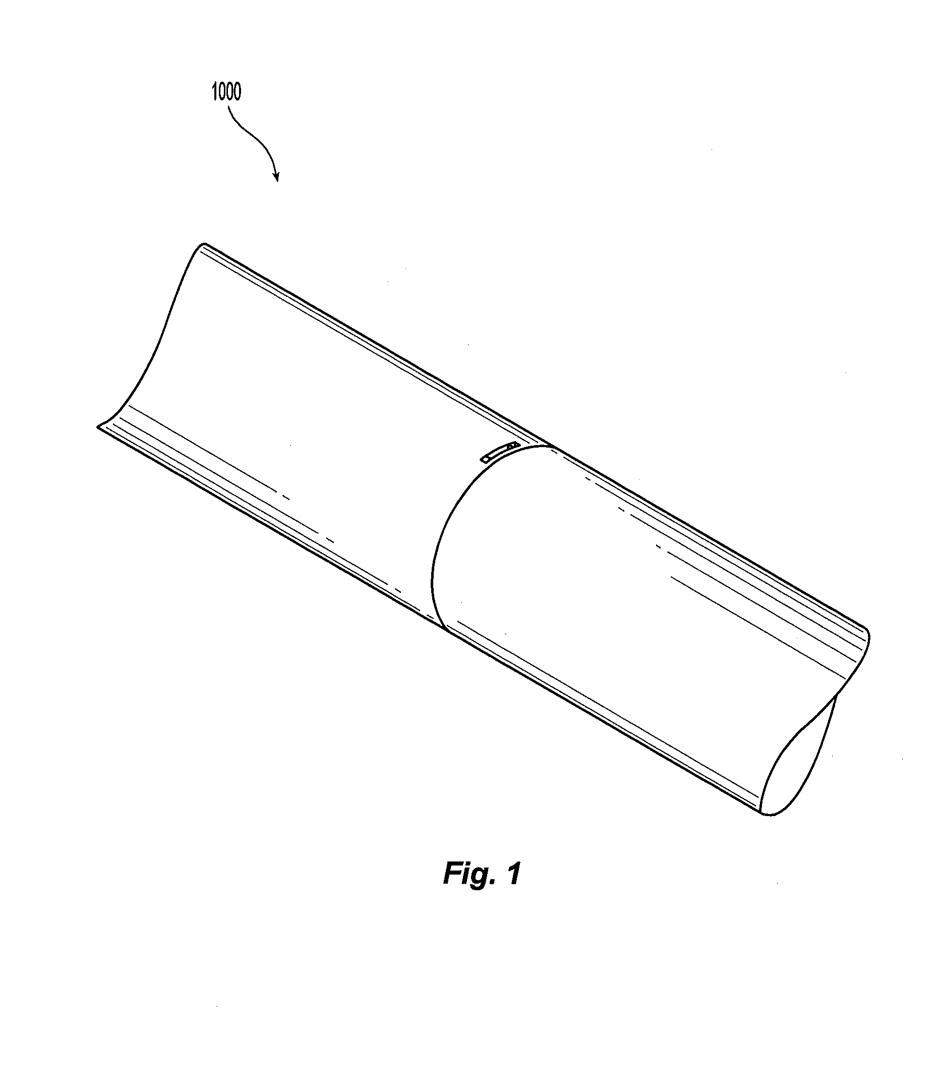
[0026]Turning initially to FIG. 1, a medical tube assembly 1000 is shown. Medical tube assembly 1000 may have a substantially tubular profile, i.e., medical tube assembly 1000 is an elongate member with a substantially circular cross-sectional profile. In some embodiments, medical tube assembly 1000 may have other shapes, and cross-sectional profiles, e.g., square, rectangular, or ovoid. Those skilled in the art will envision other suitable shapes and configurations for medical tube as...


PUM


Abstract

A medical tube assembly is disclosed, and includes a first tube portion defining a longitudinal axis, a second tube portion, and a coupling member. The coupling member is configured to couple the first tube portion and the second tube portion. The coupling member is configured to circumferentially engage the second tube portion and has a protrusion configured to engage a portion of the first tube portion. The second tube portion is configured to transition the coupling member from a resting condition to a coupling condition. The coupling member is configured to engage the first tube portion in the coupling condition.

Description

CROSS-REFERENCE TO RELATED APPLICATIONS[0001]This application claims the benefit of and priority to U.S. Provisional Patent Application No. 61 / 805,990, filed Mar. 28, 2013, the entire disclosure of which is incorporated by reference herein.BACKGROUND[0002]1. Technical Field[0003]The present disclosure relates to tube assemblies for use in medical procedures. More specifically, the present disclosure relates to a tube assembly incorporating multiple tube portions and a coupling member to couple the multiple tube portions together.[0004]2. Background of Related Art[0005]Various types of tube assemblies are known in the art, and are commonly used, for example, to transfer fluids to, from, and within portions of a human or animal. Tube assemblies, such as catheter tubes, are employed in, e.g., dialysis procedures, delivery of treatment fluids, and drainage.[0006]Some tube assemblies incorporate multiple interconnected components, i.e., some tube assemblies include multiple tube portions...

Claims


Application Information

Patent Timeline
Patent Type & Authority Applications(United States)
IPC IPC(8): A61M39/10F16L37/12
CPCF16L37/1225A61M39/10A61M39/08F16L37/1235
Inventor CABRERA, RAMIRONELSON, ANNE
Owner TYCO HEALTHCARE GRP LP
Why Eureka
Try Eureka