Grinding apparatus

a technology of grinding machine and rotary joint, which is applied in the direction of grinding drive, grinding machine components, manufacturing tools, etc., can solve the problems of not being able to guide the grinding water into the rotary joint while the workpiece is being pushed, the grinding water cannot be drawn from the holding surface, and the grinding water cannot be led into the rotary joint. , to achieve the effect of efficient introduction

Active Publication Date: 2018-01-25
DISCO CORP
View PDF17 Cites 6 Cited by
  • Summary
  • Abstract
  • Description
  • Claims
  • Application Information

AI Technical Summary

Benefits of technology

[0009]Therefore, one task that the grinding apparatus needs to achieve is that even if it is difficult to guide grinding water into the rotary joint from the holding surface of the holding table, the grinding water should efficiently be led into the rotary joint to prevent the

Problems solved by technology

In some grinding modes, however, the grinding water cannot be led into the rotary joint while the workpiece is being ground.
In this case, since the entire holding surface of the holding table is covered with the protective tape, the grinding water cannot be drawn in from the holding surface and hence cannot be guided into the rotary joint.
Furthermore, if the suction force generated by the suction source is intensified to hold the workpiece more strongly on the holding surface of the

Method used


Image

  • Grinding apparatus
  • Grinding apparatus
  • Grinding apparatus

Examples


Embodiment Construction

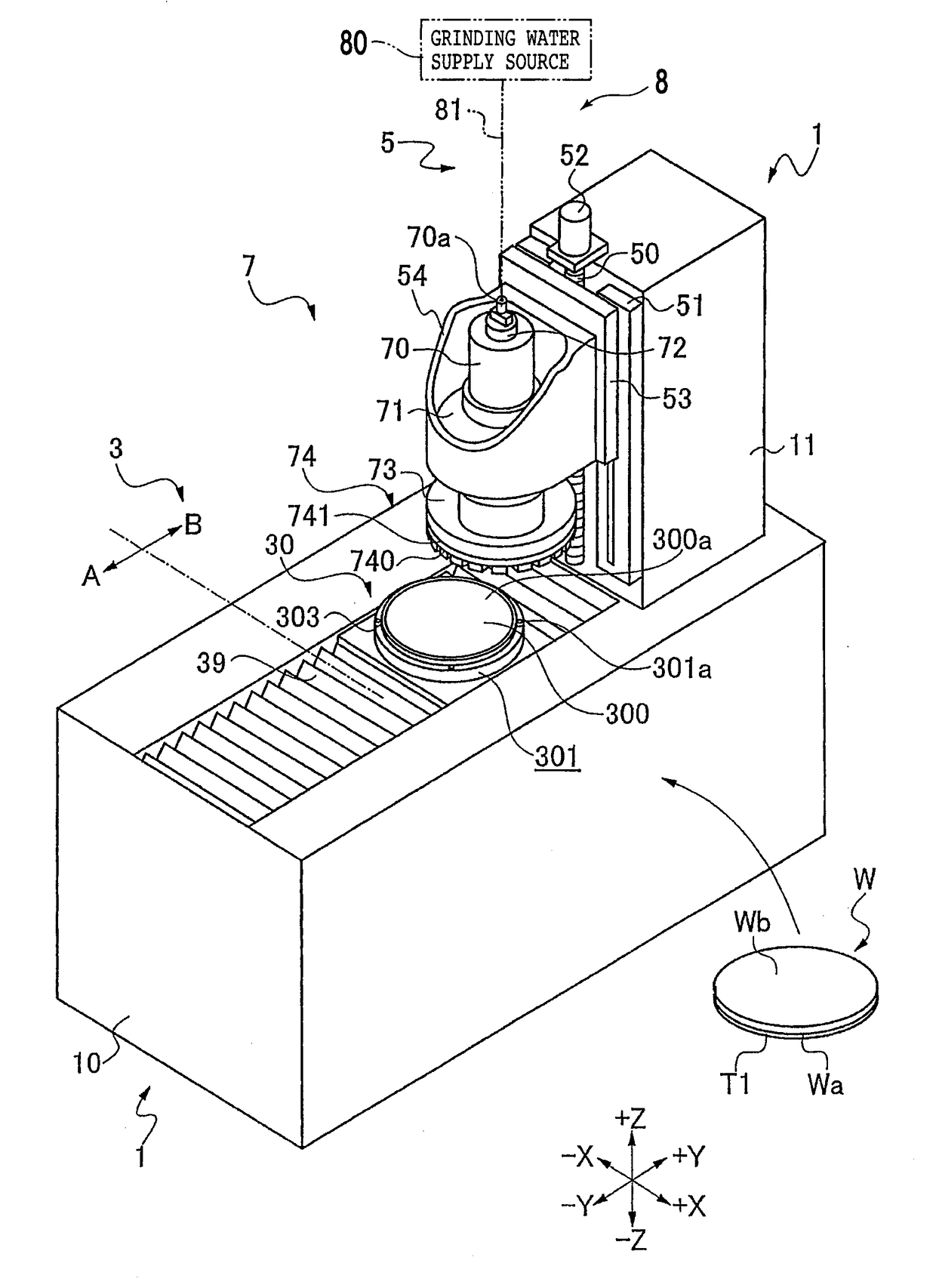
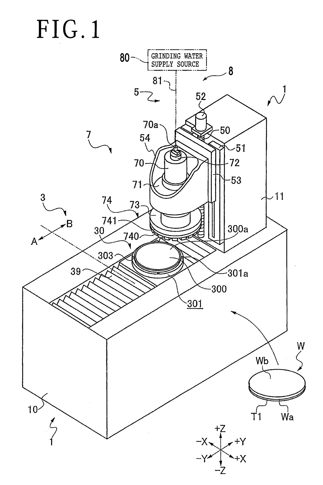
[0017]FIG. 1 illustrates in perspective a grinding apparatus 1 according to a preferred embodiment of the present invention. The grinding apparatus 1 includes holding means 3 for holding a workpiece W on a holding table 30 thereof and grinding means 7 for grinding the workpiece W held on the holding table 30. The grinding apparatus 1 has a base 10 divided into a front section (extending in a −Y direction) serving as a loading / unloading region A where the workpiece W can be loaded on and unloaded from the holding means 3 and a rear section (extending in a +Y direction) serving as a grinding region B where the workpiece W held on the holding means 3 is ground by the grinding means 7.

[0018]The grinding apparatus 1 includes a column 11 vertically mounted in the grinding region B of the base 10 and grinding feed means 5 mounted on a side surface of the column 11 which faces in the −Y direction, for grinding-feeding the grinding means 7 vertically toward and away from the holding means 3....


PUM


Abstract

A grinding apparatus includes a holding unit including a holding table having a holder for holding a workpiece and a grinding water suction part for drawing in grinding water outside of the holder, a rotational shaft having an end fixed centrally to a bottom surface of the holding table, a tubular rotary joint surrounding the rotational shaft, and a motor rotating the rotational shaft about its own axis. The rotational shaft has a first suction channel held in fluid communication with the holder of the holding table and a second suction channel held in fluid communication with the grinding water suction part. The rotary joint has a communication channel by which the first suction channel and the second suction channel are held in fluid communication with at least a suction source.

Description

BACKGROUND OF THE INVENTIONField of the Invention[0001]The present invention relates to a grinding apparatus for grinding a workpiece held on a holding table while supplying grinding water to the workpiece.Description of the Related Art[0002]Plate-like workpieces such as semiconductor wafers or the like are ground to a predetermined thickness by a grinding apparatus (see, for example, Japanese Patent Laid-Open No. 2001-287141) and then divided by a cutting apparatus or the like into individual device chips, which will be used in various types of electronic devices or the like. The grinding apparatus has a holding table for holding a workpiece on its upper holding surface under suction, with a rotational shaft having an upper end coupled to the lower surface of the holding table.[0003]The holding surface of the holding table is held in fluid communication with a suction source such as a vacuum generator or the like through a suction channel defined in the rotational shaft, for exampl...

Claims


Application Information

Patent Timeline
IPC IPC(8): B24B7/22B24B47/06B24B41/06B24B47/08
CPCB24B7/228B24B47/08B24B49/10B24B41/06B24B55/02B24B47/06B24B41/061B24B55/03B24B57/00B24B55/12B24B37/30B24B37/20H01L21/304
Inventor MIYAMOTO, HIROKI
Owner DISCO CORP
Why Eureka
Try Eureka