Work vehicle

a technology for working vehicles and vehicles, applied in transportation items, pedestrian/occupant safety arrangements, roofs, etc., can solve the problems of insufficient space for disposing of drive units, inability to carry out dumping operations of load-carrying platforms, and troublesome preliminary operations, so as to enhance the ambient air feeding function, enhance the heat exchange function, and reduce the length of the vehicle body.

Active Publication Date: 2013-02-19
KUBOTA CORP
View PDF36 Cites 29 Cited by
  • Summary
  • Abstract
  • Description
  • Claims
  • Application Information

AI Technical Summary

Benefits of technology

[0020]With the above construction, with a simple operation of switching over the posture of the rear seat, it is possible to open up or close the upper side of the drive unit disposed downwardly of this rear seat. Therefore, there is no need for the preliminary operation in opening the upper side of the drive unit, and the upper side of the drive unit can be opened / closed easily. As a result, the trouble required for maintenance and inspection of the drive unit can be alleviated.
[0049]Preferably, at positions of the floor face on the laterally outer sides of the vehicle body, there are provided laterally outer vertical walls extending continuously from the rear vertical wall, said each laterally outer vertical wall defining a laterally oriented ventilation opening allowing introduction of ambient air from the laterally outer sides to the inner side. This construction allows even more efficient introduction of ambient air.

Problems solved by technology

However, in the case of this conventional technique, each time there arises the need for maintenance operation, it is needed to open up the upper side of the drive unit by moving the load-carrying platform together with the partitioning member.
And, this preliminary operation would be troublesome.
Moreover, during a two rows seat layout mode using both the driver's seat and the rear seat, the dumping operation of the load-carrying platform cannot be carried out.
However, with the work vehicle according to the Japanese Patent Application “Kokai” No. 2005-178782, if the loading function and the safety performance of the vehicle are to be improved, without significantly changing the size of the entire vehicle body, there arises a problem as follows.
This inevitably requires displacement of the position of the rear seat toward the rear side of the vehicle body.
However, if the rear seat is provided with such offset arrangement to the rear side of the vehicle body, simple extension, if made, in the length of the vehicle body by an amount corresponding to one row of seat, would be insufficient for ensuring disposing space of the drive unit, etc.
This is because, with increase in the loading capacity, it becomes necessary to improve the engine output, which results in turn to increase in the size of the engine per se, and sizes of the transmission case and the peripheral devices and results also in enlargement of the radiator which now has an increased cooling area for providing improved cooling function.
Therefore, the technique cannot provide any practical solution.
In this case; however, the vehicle body or other devices present on the front side of the air introducing face of the radiator would interfere with the air flow, thus creating a new problem of appropriate introduction of ambient air to the entire air introducing face becoming difficult.
Conversely, if the wide air introducing face is disposed under the rear facing posture, there is the possibility of occurrence of reverse flow of the exhaust air blown to the front side from the radiator in association with traveling of the vehicle body; hence, this arrangement too is undesirable.

Method used


Image

  • Work vehicle
  • Work vehicle
  • Work vehicle

Examples


first alternative embodiment

of the Invention

[0248]In the foregoing embodiment, after the front bottom portion 42 together with the front wall portion 46 is raised rearward and folded, the right and left front side walls 45 are folded to the rear side. Instead, it is possible to employ a different folding order as the order of folding the front wall portion 46, the front bottom portion 42 and the right and left front side wall portions 45. For instance, after folding the right and left front side wall portions 45 to the rear side, the front bottom portion 42 together with the front wall portion 46 can be raised to the rear side and then folded.

[0249]In the foregoing embodiment, by folding the front wall portion 46, the front bottom portion 42 and the right and left front side wall portions 45 rearward, the extended state and the contracted state of the load-carrying platform 40 are realized. Instead, it is possible to employ for the load-carrying platform 40 further constructions shown in FIG. 32A and FIG. 32B....

second alternative embodiment

of the Invention

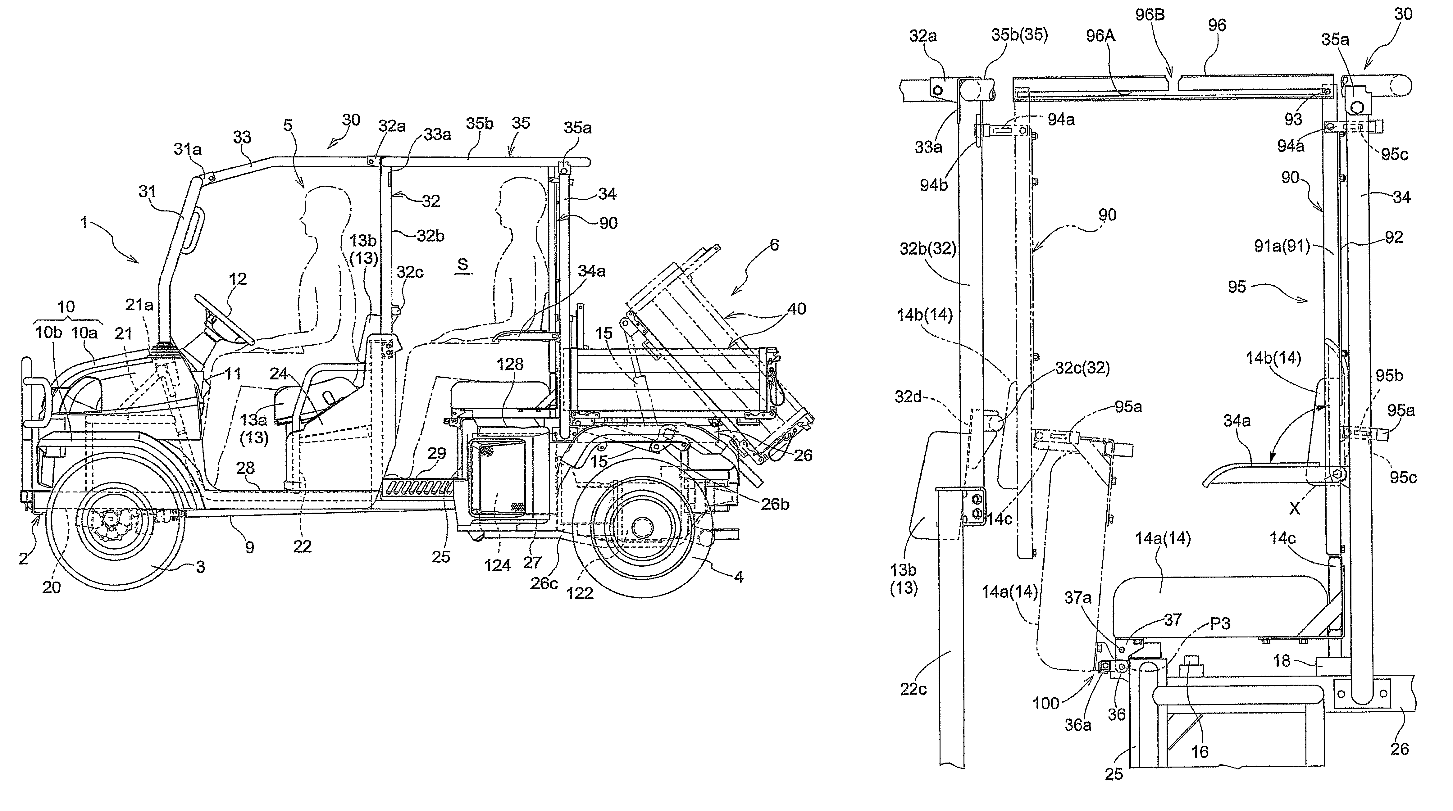
[0255]In the foregoing embodiment, as the partitioning member 90 is configured to be slidable along the rail members 96, the partitioning member 90 is switchable in position between the forwardly displaced position and the rearwardly displaced position. Instead, a different arrangement can be employed for rendering the partitioning member 90 switchable in position between the forwardly displaced position and the rearwardly displaced position. Specifically, the partitioning member 90 can be constructed as detachably attached type such that the partitioning member 90 at the forwardly displaced position and the rearwardly displaced position can be detachably attached to the ROPS 30 and with detachment of the partitioning member 90 fixed to the ROPS 30 at one of the forwardly displaced position and the rearwardly displaced position, this removed partitioning member 90 is fixed to the ROPS 30 at the other of the forwardly displaced position and the rearwardly displaced po...

third alternative embodiment

of the Invention

[0256]In the foregoing embodiment, the partitioning member 90 at the forwardly displaced position and the rearwardly displaced position is fixed to the ROPS 30. Instead, it is possible to employ a further construction wherein the partitioning member 90 at the forwardly displaced position and the rearwardly displaced position is fixed to the vehicle body. For instance, the partitioning member 90 at the forwardly displaced position and the rearwardly displaced position can be fixed to the vehicle body frame 2, the front seat supporting panel 24, the rear deck plate 29, etc. Or, a further frame member (not shown) other than the ROPS 30 can be extended from the vehicle body frame 2, the front seat supporting panel 24, the rear deck plate 29, etc. and to this frame member, the partitioning member 90 at the forwardly displaced position and the rearwardly displaced position can be fixed.

[0257]Further alternatively, the partitioning member 90 at one of the forwardly displace...


PUM


Abstract

A pick-up style work vehicle includes a rollover protection structure (ROPS), a seat section including a forward driver's seat and a rear seat, and a rear seat posture changing mechanism for changing the rear seat in its position between a first posture where the rear seat is in a non-use condition and a second posture where the rear seat is in a use condition. A fore / aft length of the rear seat in the first posture is shorter than the fore / aft length of the rear seat in the second posture. The work vehicle also includes a partitioning member for partitioning the seat section from a space behind the seat section with the partitioning member being supported by the ROPS. The partitioning member is movable with being supported by the ROPS between a rearwardly displaced position immediately behind the rear seat and a forwardly displaced position moved forward from the rearwardly displaced position.

Description

CROSS REFERENCE TO RELATED APPLICATIONS[0001]This application is a continuation of U.S. application Ser. No. 12 / 420,556 filed on Apr. 8, 2009, which claims priority to Japanese Application Nos. 2008-192671; 2008-192672; 2008-192673; and 2008-192674 each filed on Jul. 25, 2008.BACKGROUND OF THE INVENTION[0002]1. Field of the Invention[0003]The present invention relates to a work vehicle comprising a vehicle body frame extending in the fore / aft direction, a passenger's section included in the vehicle body frame, a driver's seat disposed forwardly of the passenger's section, and a drive unit under which the vehicle body frame is disposed, the drive unit having an engine.[0004]2. Description of the Related Art[0005]The work vehicle of the above-noted type is conveniently used not only for transportation of construction material or the like, but also for transportation of passengers.[0006]And, in such work vehicle, if the drive unit is disposed under the vehicle body frame, this can elim...

Claims


Application Information

Patent Timeline
Patent Type & Authority Patents(United States)
IPC IPC(8): B62D25/00
CPCB62D21/186B62D23/005B62D33/037B62D25/088B62D33/02B62D33/08B62D33/0625
Inventor NAKAMURA, NORIMIIMANISHI, RYOUZOUFUJIWARA, KOJIKOBAYASHI, MITSUGUHIROOKA, YOSHIMINAKAMURA, TAROSHIMAMURA, TERUO
Owner KUBOTA CORP
Why Eureka
Try Eureka