Motor vehicle door lock

a technology for motor vehicles and door locks, applied in the field of motor vehicle door locks, can solve the problems of increased opening force and difficult actuation of the catch mechanism, and achieve the effect of preventing dust from entering

Active Publication Date: 2014-10-02
KIEKERT AG
View PDF8 Cites 3 Cited by
  • Summary
  • Abstract
  • Description
  • Claims
  • Application Information

AI Technical Summary

Benefits of technology

[0022]One embodiment of the invention contains a linear elevation on which the rotary latch rests. In particular, the rotary latch rests on said linear elevation in every position. The linear elevation commences preferably with a stage or a projection of the damping element or of the component with the abutment surface and extends, in particular, initially parallel to an infeed section of the lock. On the inside base of the infeed section, the arch-shaped elevation departs in one embodiment from the infeed section and extends in an arch shape initially around this internal end or this base of the infeed section. The linear elevation furthermore contributes to preventing dust from entering the lock. The linear elevation is, in particular, part of a wall of the lock housing.

Problems solved by technology

By maintaining a small gap, frictional forces are avoided which could make the actuation of the catch mechanism more difficult.
First of all, this arrangement prevents any dust from settling on the blocking surface of the rotary latch in the opened position, which could result in greater opening forces.

Method used


Image

  • Motor vehicle door lock
  • Motor vehicle door lock
  • Motor vehicle door lock

Examples


Embodiment Construction

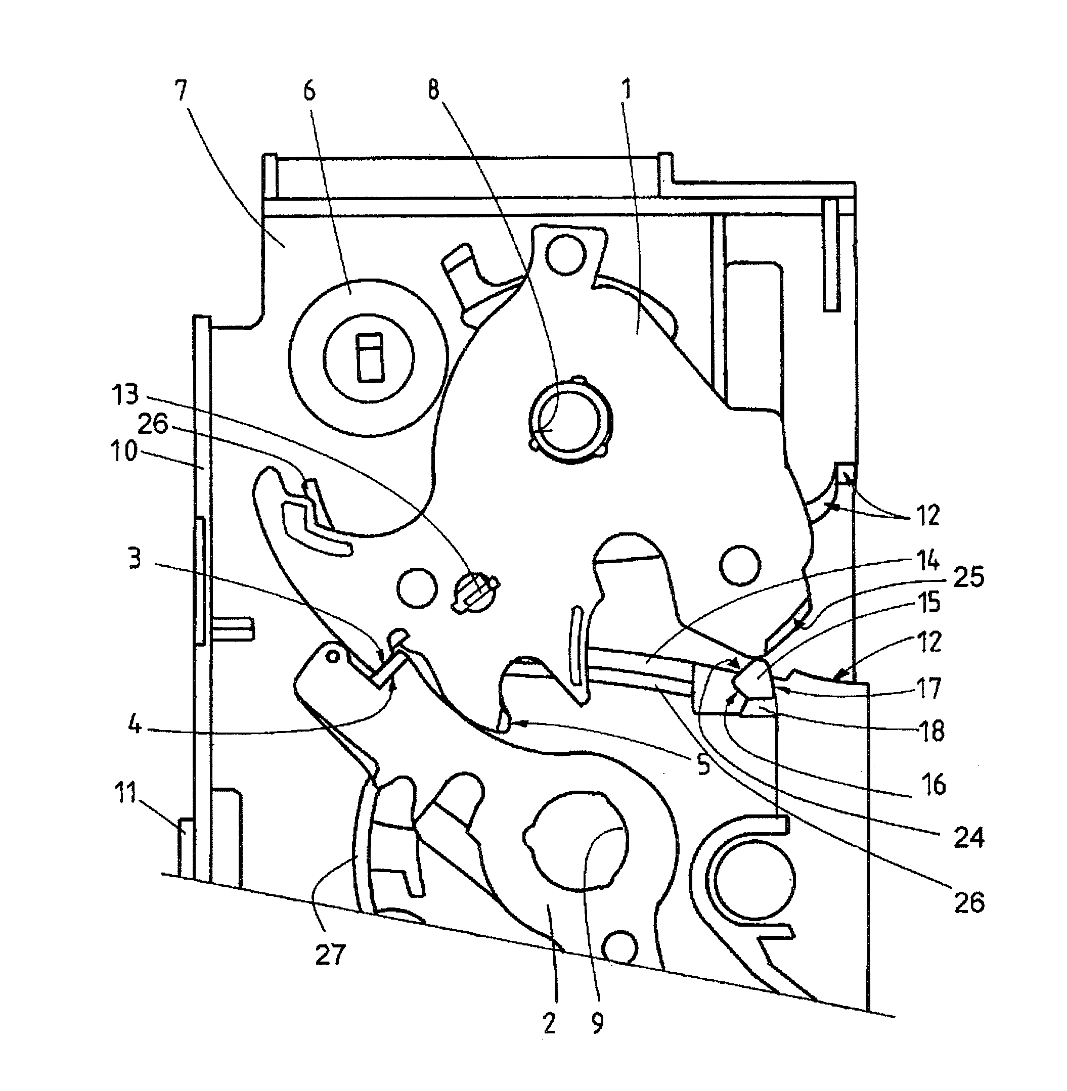
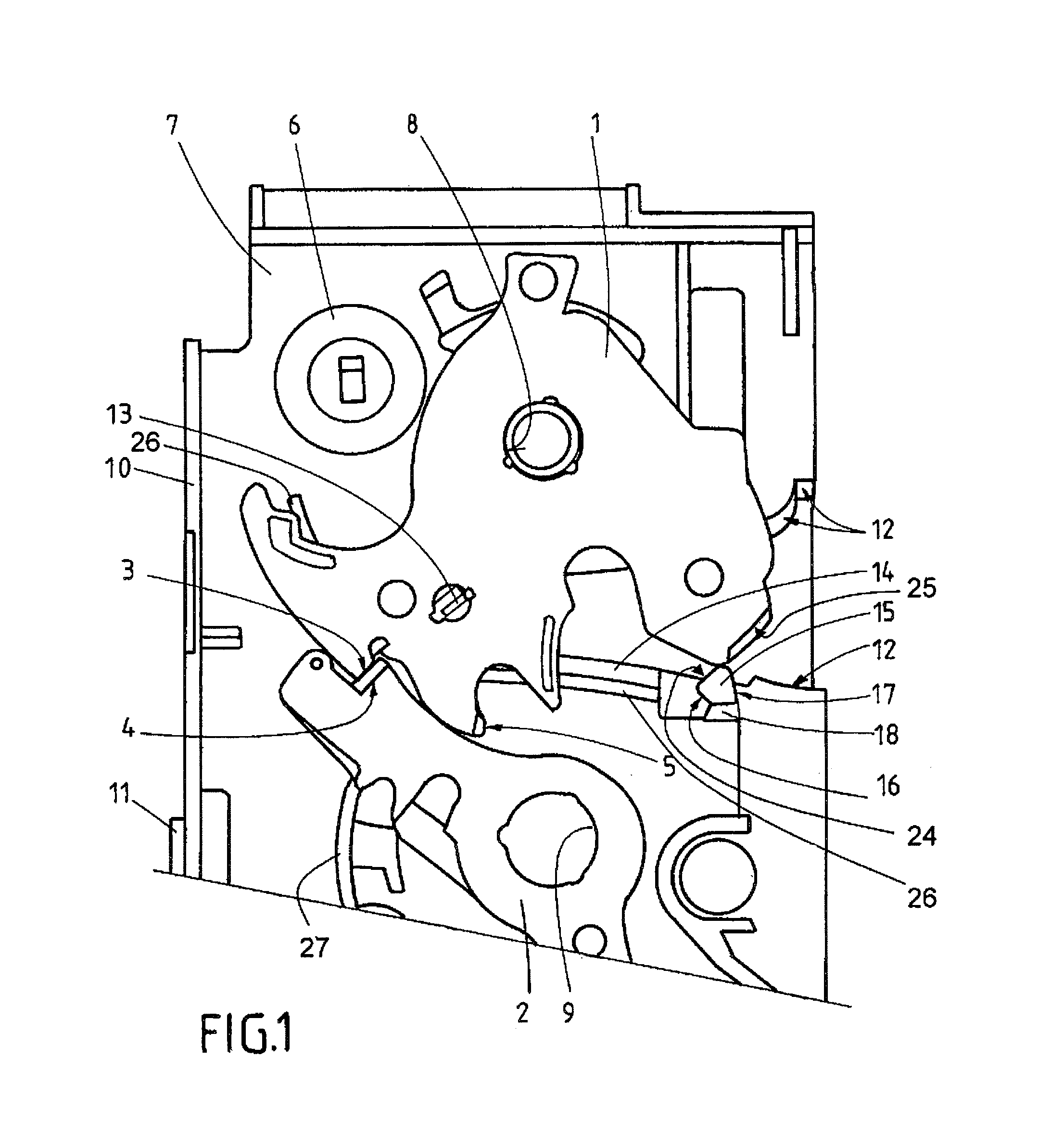
[0027]FIG. 1 shows a catch mechanism with a rotatably mounted rotary latch 1 and a rotatably mounted pawl 2. In FIG. 1, the catch mechanism is in the intermediate closed position. A metal blocking surface 3 of the rotary latch 1 is pressed against a metal blocking surface 4 of the pawl 2. The rotary latch 1 can therefore not be turned counter clockwise in the opened position.

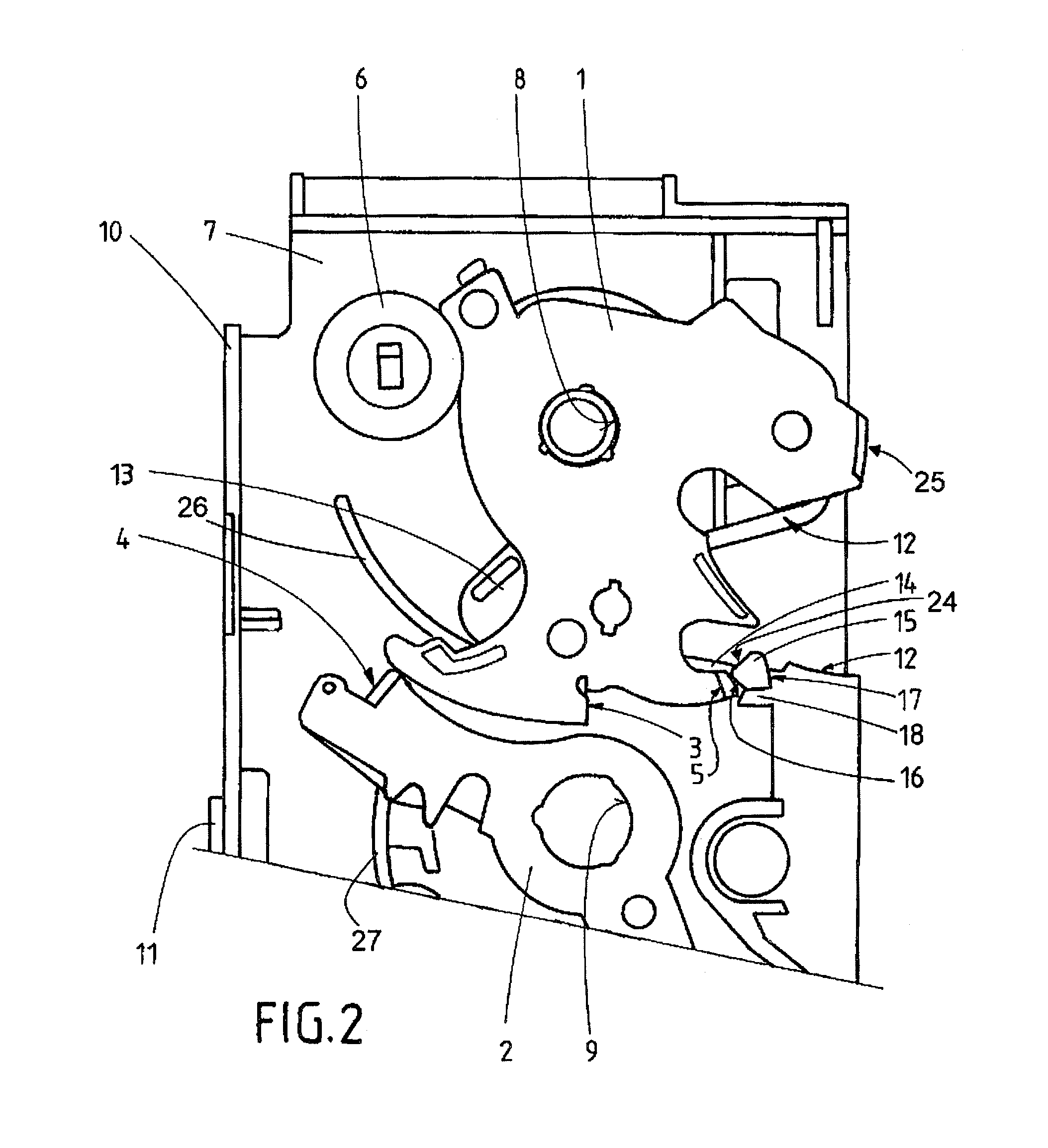
[0028]The rotary latch 1 contains a further metal blocking surface 5, pressed against the blocking surface 4 of the pawl 2 in the fully closed position. Where the rotary latch 1 shown in FIG. 1 is turned further in clockwise direction, the catch mechanism finally assumes this fully closed position. A stop 6 formed by a ring made from elastic material, limits the rotary movement of the rotary latch 1 in clockwise direction as well as in counter-clockwise direction, as shown in FIG. 2.

[0029]A wall 7 of a plastic lock housing is located below the rotary latch 1 shown in FIG. 1. Below this plastic wall 7 a metal and...


PUM


Abstract

A lock including a catch mechanism made up of a rotary latch and catch for latching the rotary latch. The rotary latch and catch have blocking surfaces for latching purposes. In the latched state, the blocking surface of the rotary latch rests on the blocking surface of the catch, and this prevents the rotary latch from being able to rotate in the direction of the open position. The lock also includes a component with an abutment surface, against which the blocking surface of the rotary latch butts in the open position of the catch mechanism. This abutment prevents the situation where, in the open position, dust can pass onto the blocking surface of the rotary latch. In addition, the abutment reduces the penetration of dust into the catch mechanism. An increase in the opening forces as service life increases is thus avoided.

Description

[0001]RELATED APPLICATION DATA[0002]This application is a continuation of U.S. application Ser. No. 13 / 982,885 filed Jul. 31, 2013 which is a National Phase of PCT / DE2012 / 000056 filed Jan. 24, 2012 which claims priority of German Application No. 10 2011 003 410.2 filed Jan. 31, 2011, are of which are hereby incorporated herein by reference in their entireties.BACKGROUND[0003]The invention relates to a lock for a door or tailgate / gate with a catch mechanism comprising a rotary latch and a pawl for latching the rotary latch. Such a lock is, for instance, known from DE 103 20 457 A1.[0004]The aforementioned lock allows temporary locking of openings in motor vehicles or buildings with the aid of doors or tailgates / gates. In the closed state of such a lock, the rotary latch grips around the, in particular, bow-shaped locking bolt, which in case of a vehicle is generally attached to the car body. When the rotary latch reaches a locked position after having been pivoted from an open positi...

Claims


Application Information

Patent Timeline
Patent Type & Authority Applications(United States)
IPC IPC(8): E05B85/26
CPCE05B85/26E05B77/34E05B77/38Y10T292/1075
Inventor GRAUTE, LUDGERKIPPES, THOMAS
Owner KIEKERT AG
Why Eureka
Try Eureka