
Image reading apparatus

Inactive Publication Date: 2014-10-02
SEIKO EPSON CORP
View PDF10 Cites 6 Cited by
  • Summary
  • Abstract
  • Description
  • Claims
  • Application Information

AI Technical Summary

Benefits of technology

The technical effects of the patent text are as follows: 1. The image reading apparatus has first and second opening and closing bodies, with the first body having a document platen for placing a document and the second body being a cover for opening and closing over the document platen. This configuration allows for easy handling and positioning of the document for reading. 2. The second body can be displaced in a direction that advances and retreats with respect to the document platen, which allows for adjustment of its position based on the thickness of the document placed on the platen, ensuring uniform pressure and a satisfactory reading result. 3. The lower structure of the apparatus is also preferably provided with a recording component for performing recording on a medium.

Problems solved by technology

For example, in a case in which the scanner body and the document cover are both structured so as to open towards the rear side of the recording device, if the scanner body is opened while the document cover is in an open state, the document cover disadvantageously opens further towards the rear side of the recording device and, thus, a large space will be required at the back of the device.
Furthermore, in a case in which the device is installed without sufficient space at its back, when the scanner body is opened while the document cover is in an open state, the document cover may hit an object, such as a wall, at the back of the device and the document cover may become damaged.

Method used


Image

  • Image reading apparatus
  • Image reading apparatus
  • Image reading apparatus

Examples


Embodiment Construction

[0037]An exemplary embodiment of the invention will be described next with reference to the drawings.

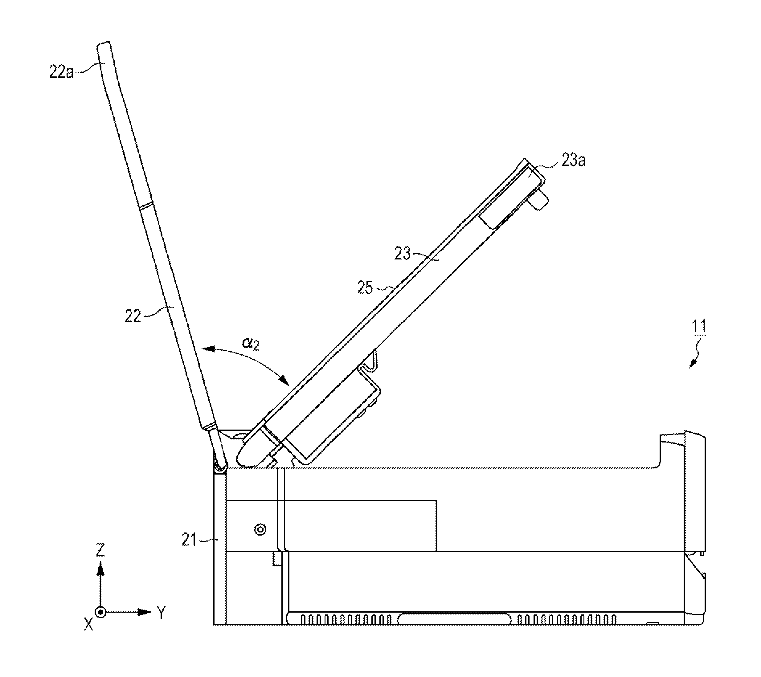
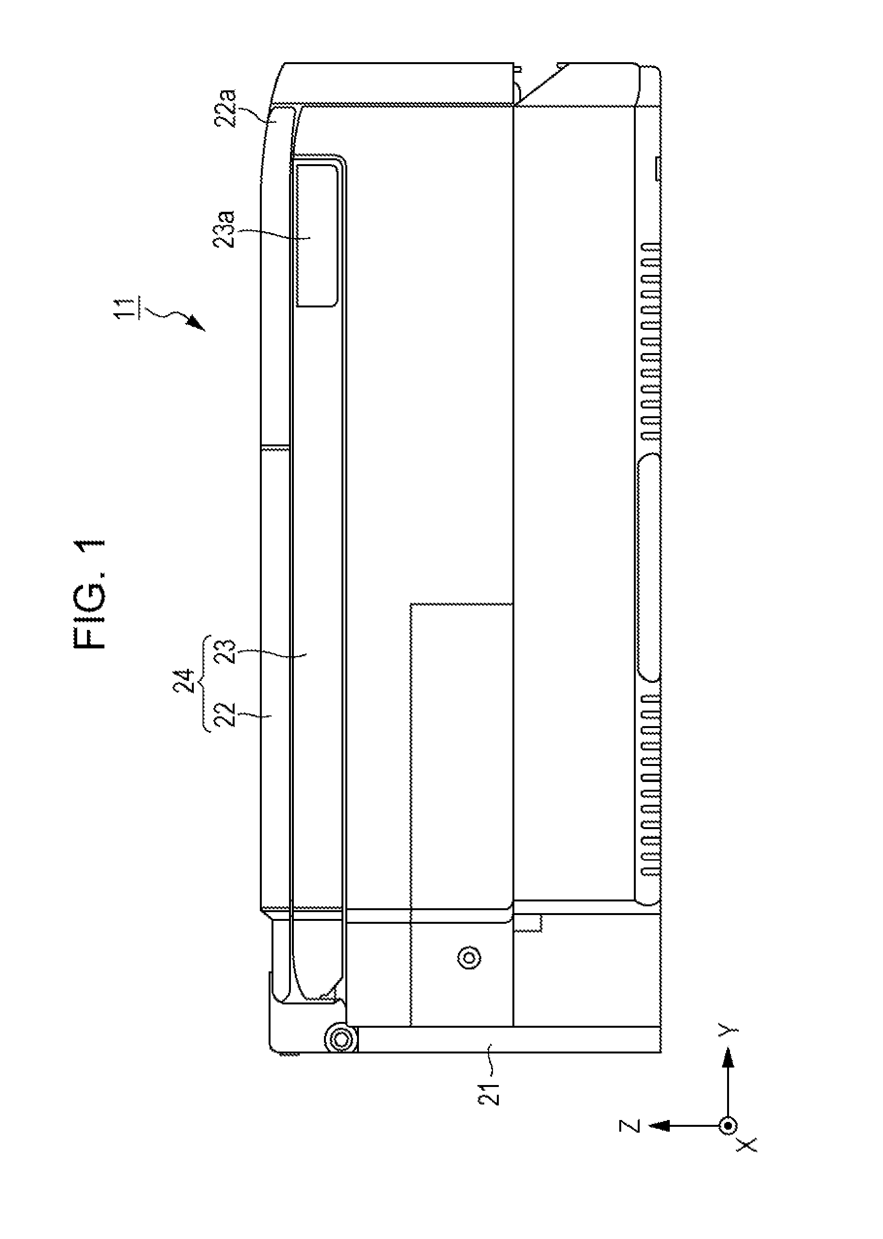
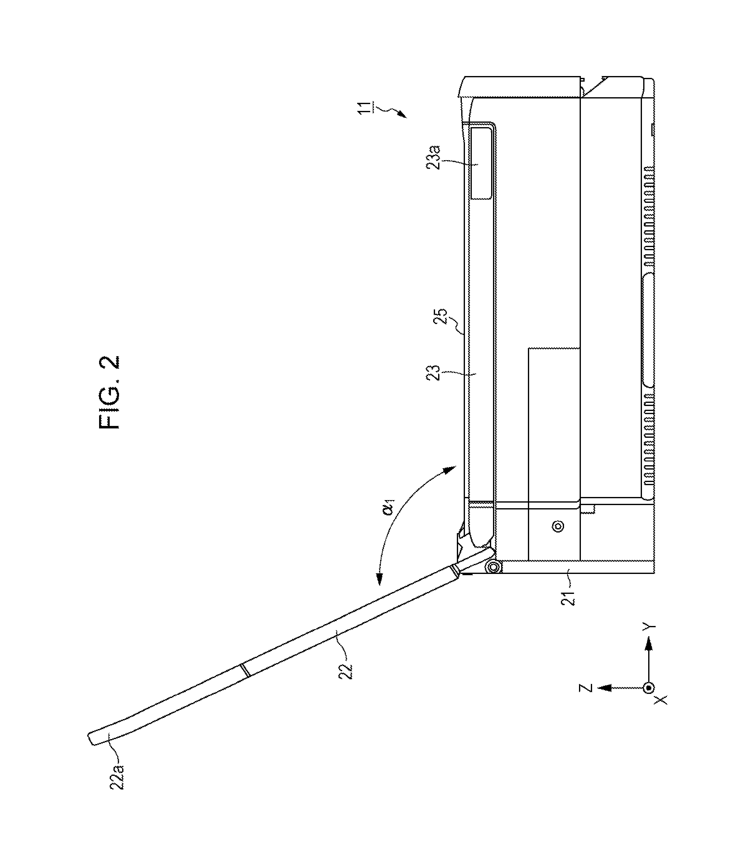
[0038]FIGS. 1 to 3 are left-side views each illustrating an appearance of a multifunction printer 11 that is an example of an image reading apparatus according to the invention. FIG. 1 is a left-side view illustrating an appearance of the multifunction printer 11 in which a cover 22 and a scanner body 23 are closed. FIG. 2 is a left-side view illustrating an appearance of the multifunction printer 11 in which the cover 22 has been opened while the scanner body 23 is kept closed. FIG. 3 is a left-side view illustrating an appearance of the multifunction printer 11 in which the cover 22 and the scanner body 23 have been opened.

[0039]Note that, hereinafter, a Y-axis corresponds to a front-rear direction of the multifunction printer 11, a Z-axis corresponds to an up-down direction thereof, and an X-axis corresponds to a left-right direction thereof. Furthermore, hereinafter, regarding th...


PUM


Abstract

An image reading apparatus includes a lower structure; a first body that is provided in a pivotal manner with respect to the lower structure, the first body opening and closing an upper portion of the lower structure by pivotal movement; a second body that is provided in a pivotal manner with respect to the first body, the second body opening and closing, by pivotal movement, an upper portion of the first body; a first angle restricting section that restricts a maximum opening angle of the second body with respect to the first body to a first angle when the first body is in a closed state; and a second angle restricting section that restricts a maximum opening angle of the second body with respect to the first to a second angle that is smaller than the first angle when the first body is in an open state.

Description

BACKGROUND[0001]1. Technical Field[0002]The present invention relates to an image reading apparatus, a representative example of which is a scanner.[0003]2. Incorporated by Reference[0004]The entire disclosure of Japanese Patent Application No. 2013-069412, filed Mar. 28, 2013 is expressly incorporated by reference herein.[0005]3. Related Art[0006]As disclosed in JP-A-2007-336273, there are cases in which a scanner, serving as an example of an image reading apparatus, is provided above an upper portion of a recording device, serving as an example of a lower structure, that carries out recording on recording paper. In the above case, the scanner is provided in an openable and closable manner with respect to the upper portion of the recording device to allow maintenance of the recording device to be carried out. The opening and closing of the scanner is typically carried out by pivotal movement of the scanner.[0007]Furthermore, a cover that opens and closes with respect to a document ...

Claims


Application Information

Patent Timeline
IPC IPC(8): H05K5/02H04N1/00B65H7/00
CPCH04N1/00557B65H7/00H05K5/0226H05K5/0239H04N1/00554H05K5/03
Inventor KAWATA, HIDETAKAOKAZAWA, YOSHIYUKI
Owner SEIKO EPSON CORP
Learn More