
Magnetic sensor using NiFe alloy for pinned layer

a magnetic sensor and nife alloy technology, applied in the field of current, can solve the problem of inability to obtain practicable reproduction output, and achieve the effect of increasing the element area of the magnetic sensor, increasing the magnetostrictive constant of the pinned magnetic layer, and increasing the uniaxial anisotropy of the magnetic layer

Active Publication Date: 2009-10-27
TDK CORPARATION
View PDF15 Cites 1 Cited by
  • Summary
  • Abstract
  • Description
  • Claims
  • Application Information

AI Technical Summary

Benefits of technology

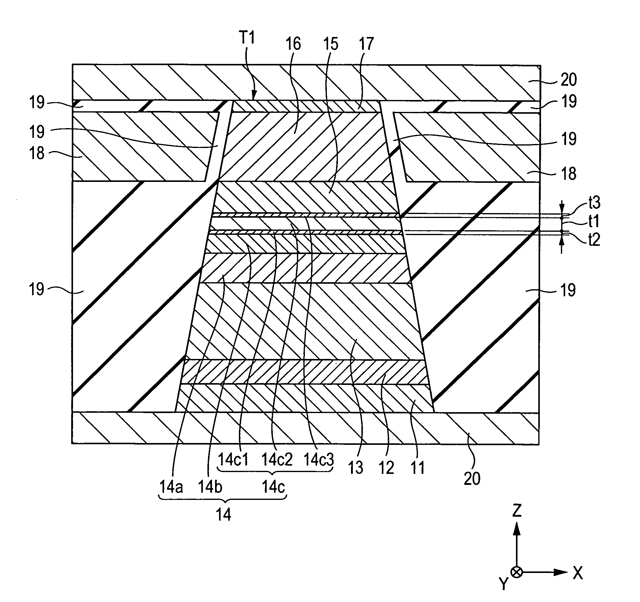
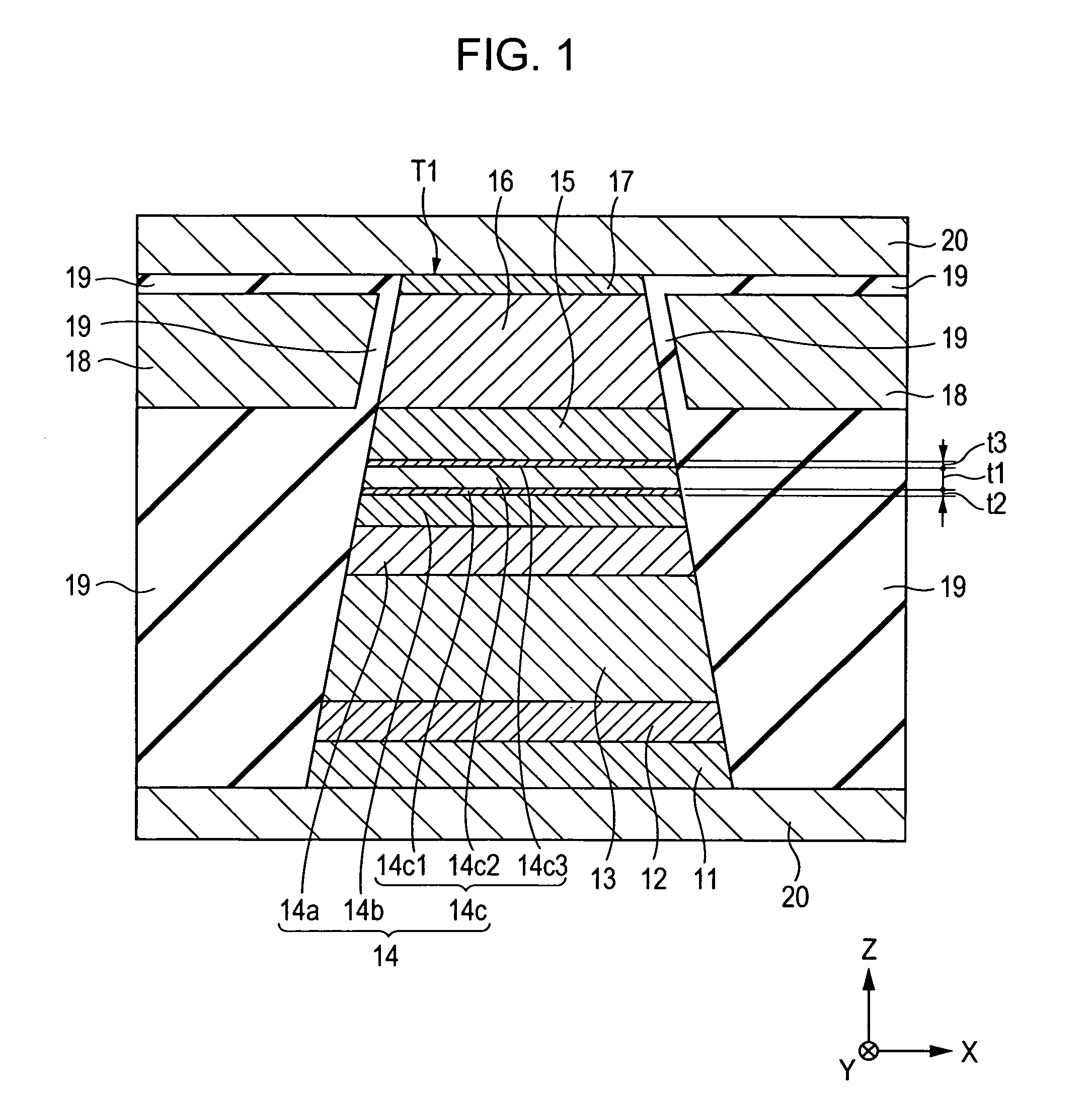
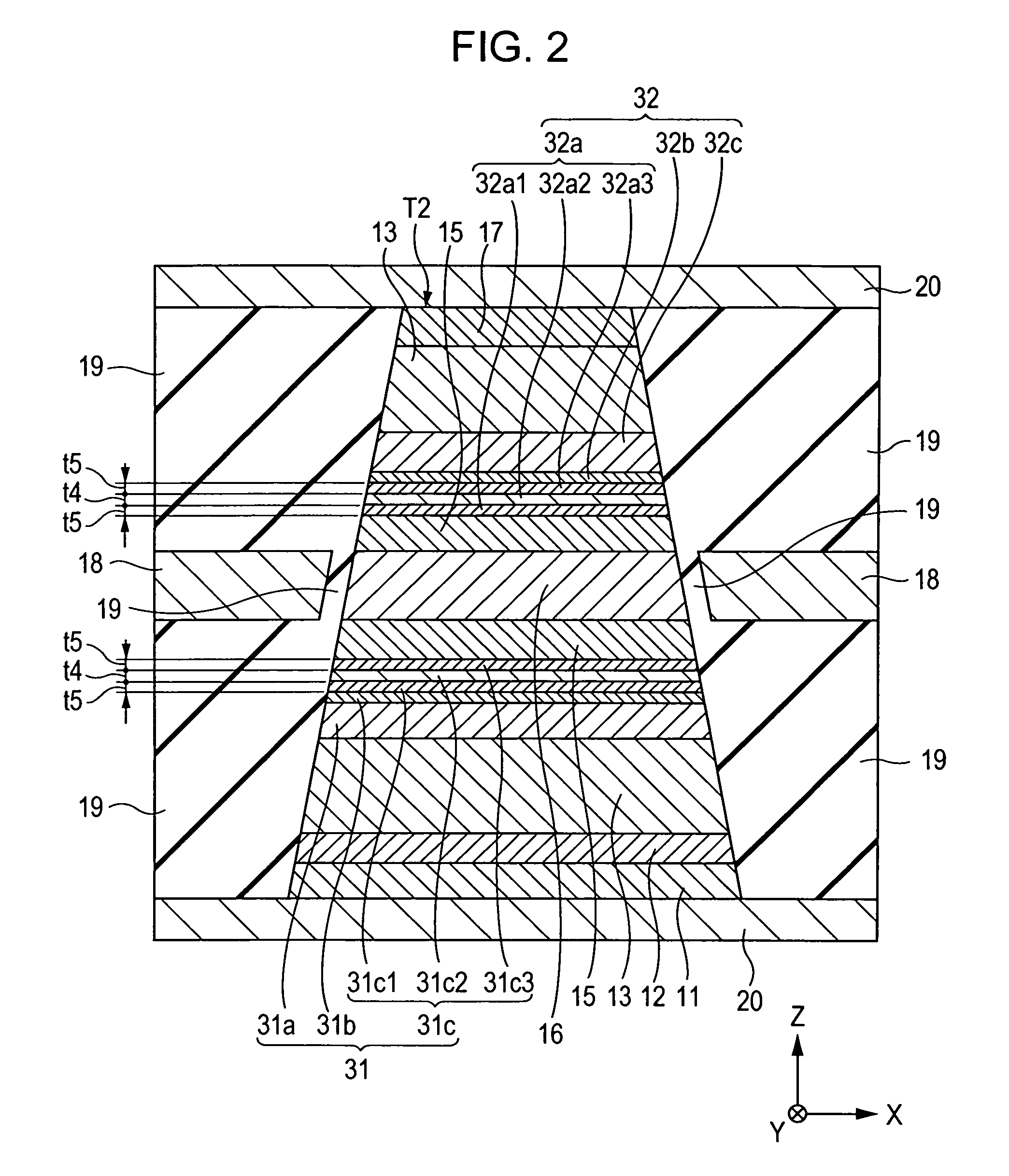
The present invention provides a magnetic sensor with a high reproduction output by forming a pinned magnetic layer with a preferable structure. The pinned magnetic layer has a NiaFeb alloy layer with a small content of Ni and iron (Fe) on an atomic percent basis. The magnetostrictive constant of the pinned magnetic layer is increased, and its uniaxial anisotropy is increased. The magnetic sensor has a three-layered structure with two CoFe layers on the top and bottom of the NiaFeb alloy layer. The pinned magnetic layer has a high magnetostrictive constant and a high uniaxial anisotropy. The magnetic sensor can be a top spin valve CPP-GMR type magnetic sensor, a bottom spin valve CPP-GMR type magnetic sensor, or a dual spin valve CPP-GMR type magnetic sensor. The pinned magnetic layer has a small content of Ni in the NiFe alloy, which increases the product ΔR·A and increases the magnetostrictive constant and uniaxial anisotropy of the magnetic sensor.

Problems solved by technology

However, even when the free magnetic layer and the pinned magnetic layer are formed using a NiFe alloy having the above composition, it has been difficult to obtain a product ΔR·A of 5 mΩ·μm2 or more, ΔR and A being the change in resistance and an element area, respectively, of a CPP-GMR type magnetic sensor in which a direct sense current is allowed to flow in a direction perpendicular to a film surface of a multilayer film, and as a result, a practical reproduction output cannot be obtained.

Method used


Image

  • Magnetic sensor using NiFe alloy for pinned layer
  • Magnetic sensor using NiFe alloy for pinned layer
  • Magnetic sensor using NiFe alloy for pinned layer

Examples


example 1

[0106]The product ΔR·A of the change ΔR in magnetic resistance and the element area A of a magnetic sensor and the magnetostrictive constant λs of second pinned magnetic layers were investigated. For this investigation, a dual spin valve magnetic sensor having a film structure shown below was formed, and the content of Ni on an atomic percent basis in a NiaFeb alloy (where a and b each indicate atomic percent, and a+b=100 is satisfied) is changed, the NiaFeb alloy being an alloy forming the second pinned magnetic layers (corresponding to the magnetic layers 31c and 32a in FIG. 2). The measurement result of the product ΔR·A and that of the magnetostrictive constant λs are shown in FIGS. 5 and 6, respectively.

[0107]The film structure contained a substrate, underlayer Ta (30 Å), seed layer NiFeCr (50 Å), antiferromagnetic layer IrMn (70 Å), pinned magnetic layer (first pinned magnetic layer Co70Fe30 (30 Å)), nonmagnetic interlayer Ru (9.1 Å), second pinned magnetic layer CoFe (10 Å), N...


PUM

PropertyMeasurementUnit
magnetizationaaaaaaaaaa
resistanceaaaaaaaaaa
areaaaaaaaaaaa

Abstract

A magnetic sensor comprising: a multilayer film which has a pinned magnetic layer, the magnetization thereof being pinned in one direction, and a free magnetic layer formed on the pinned magnetic layer with a nonmagnetic material layer provided therebetween, in which current is allowed to flow in a direction perpendicular to the surfaces of the layers forming the multilayer film, wherein the pinned magnetic layer has a NiaFeb alloy layer (where a and b each indicate atomic percent, and 0<a≦25 and a+b=100 are satisfied).

Description

BACKGROUND OF THE INVENTION[0001]1. Field of the Invention[0002]The present invention relates to current perpendicular to the plane (hereinafter referred to as “CPP”) type magnetic sensors in which a sense current is allowed to flow in a direction perpendicular to a film surface, and more particularly, relates to a magnetic sensor being able to increase ΔR·A, that is, the product of a change ΔR in resistance and an element area A.[0003]2. Description of the Related Art[0004]FIG. 7 is a partial cross-sectional view of a related magnetic sensor (spin valve thin film element) taken along a direction parallel to a face facing a recording medium.[0005]Reference numeral 1 shown in FIG. 7 indicates an underlayer made of tantalum (Ta), and on the underlayer 1, a seed layer 2 made of a metal, such as chromium (Cr), having a body-centered cubic (bcc) structure is formed.[0006]On the seed layer 2, an antiferromagnetic layer 3, a pinned magnetic layer 4, a nonmagnetic material layer 5, a free m...

Claims


Application Information

Patent Timeline
Patent Type & Authority Patents(United States)
IPC IPC(8): G11B5/33
CPCG11B5/3929
Inventor IDE, YOSUKESAITO, MASAMICHIISHIZONE, MASAHIKOHASEGAWA, NAOYA
Owner TDK CORPARATION
Learn More