
Method of forming semiconductor memory device

a technology of memory device and semiconductor, which is applied in the direction of semiconductor devices, electrical devices, transistors, etc., can solve the problems of many defects formed in the dram cell with the buried gate, and achieve the effect of simplifying the process and facilitating structur

Active Publication Date: 2021-03-09
UNITED MICROELECTRONICS CORP +1
View PDF19 Cites 0 Cited by
  • Summary
  • Abstract
  • Description
  • Claims
  • Application Information

AI Technical Summary

Benefits of technology

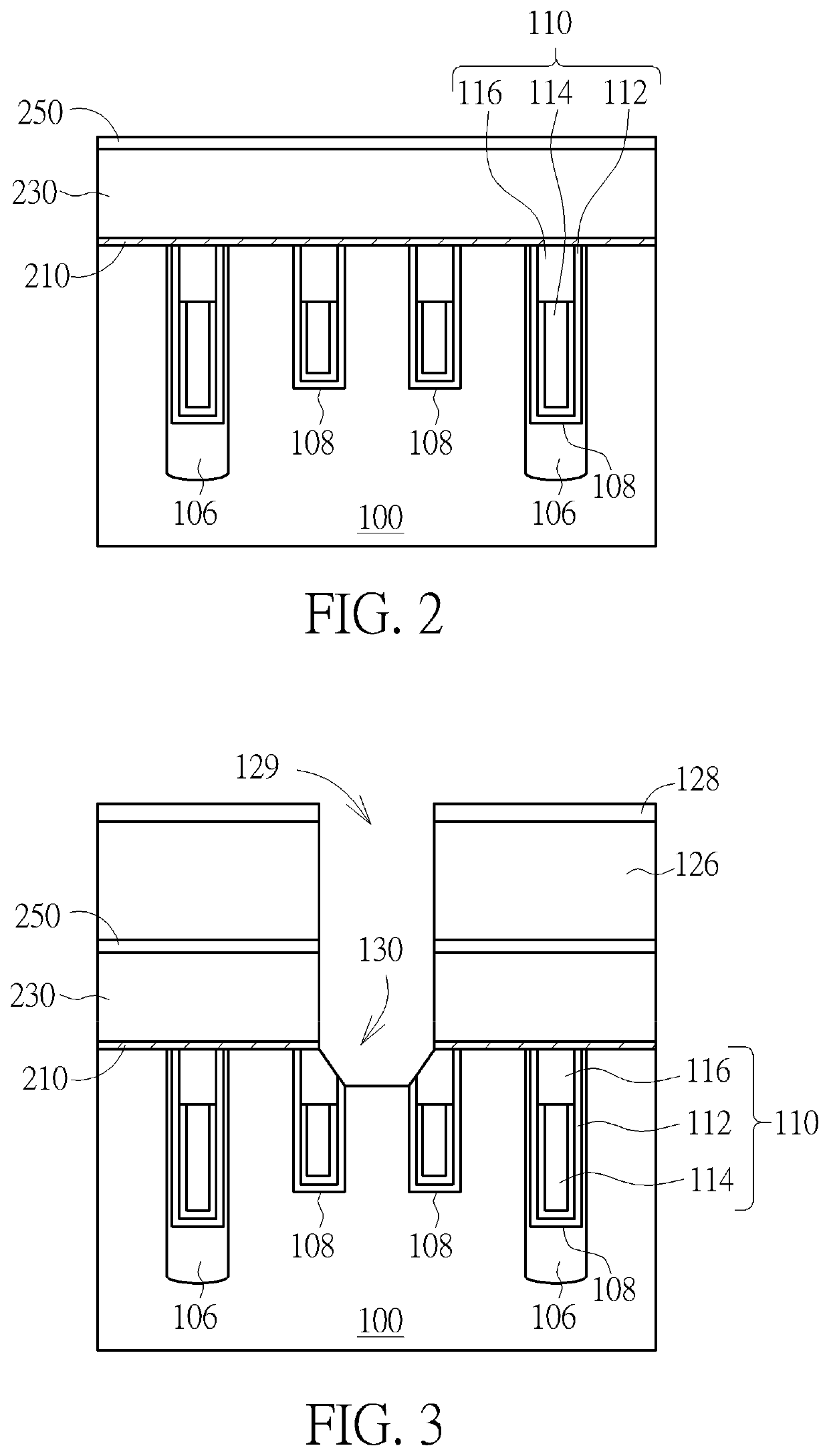
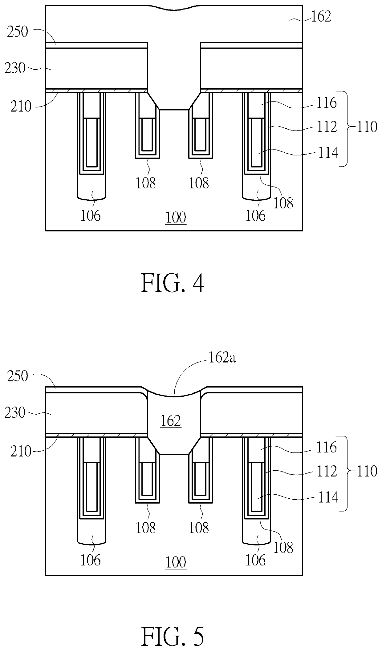
The present invention provides a method for forming a semiconductor memory device with planar top surfaces for better performance. The method uses a sacrificial layer and oxide layer or a chemical mechanical polishing process and cleaning process to remove protruding etching profiles caused by the loading effect of the conductive layer. This allows for the formation of bit line contacts and stacked layers with planar top surfaces. This method simplifies the process flow and allows for a more ideal semiconductor memory device structure.

Problems solved by technology

However, due to limitations in fabrication technologies, many defects are formed in the DRAM cell with the buried gate.

Method used


Image

  • Method of forming semiconductor memory device
  • Method of forming semiconductor memory device
  • Method of forming semiconductor memory device

Examples


Embodiment Construction

[0023]To provide a better understanding of the presented invention, preferred embodiments will be described in detail. The preferred embodiments of the present invention are illustrated in the accompanying drawings with numbered elements.

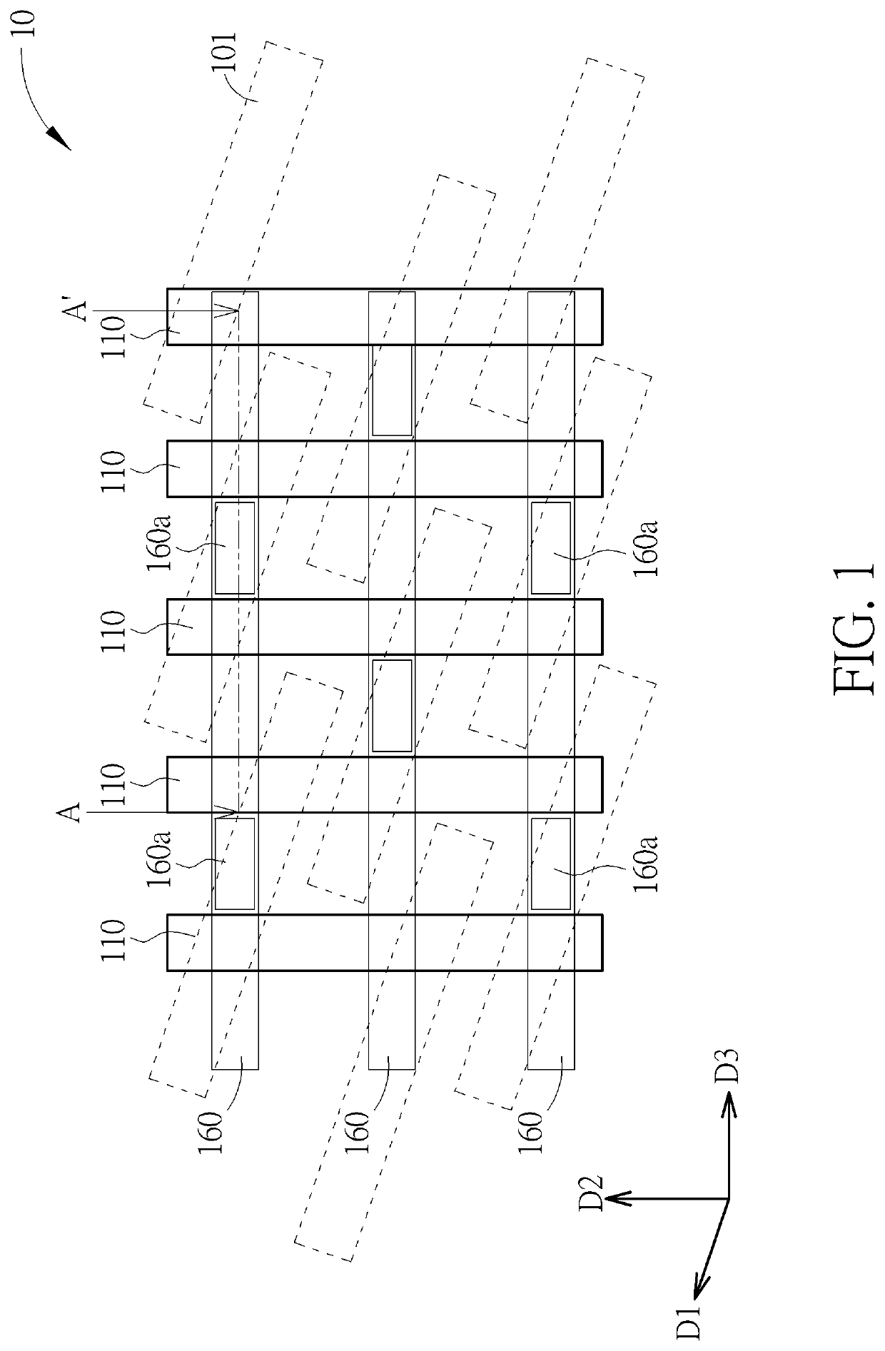
[0024]Please refer to FIG. 1, which is a schematic diagram illustrating a semiconductor memory device according to the preferred embodiment of the present invention. The semiconductor memory device for example includes a dynamic random access memory (DRAM) device 10, and which includes at least one transistor (not shown in the drawings) and at least one capacitor (not shown in the drawings), thereto serve as the smallest unit in the DRAM array for accepting signals from word lines (WLs) 110 and bit lines (BLs) 160 during the operation.

[0025]In the present embodiment, the DRAM device 10 includes a plurality of active area 101 which is parallel extended along a first direction D1, and a plurality of word lines 110 which is parallel extended along a se...


PUM

PropertyMeasurementUnit
heightaaaaaaaaaa
conductiveaaaaaaaaaa
sizeaaaaaaaaaa

Abstract

A method of forming a semiconductor memory device includes the following steps. First of all, a substrate is provided, and a plurality of gates is formed in the substrate, along a first direction. Next, a semiconductor layer is formed on the substrate, covering the gates, and a plug is then in the semiconductor layer, between two of the gates. Then, a deposition process is performed to from a stacked structure on the semiconductor layer. Finally, the stacked structure is patterned to form a plurality of bit lines, with one of the bit lines directly in contact with the plug.

Description

BACKGROUND OF THE INVENTION1. Field of the Invention[0001]The present invention relates to a method of forming a semiconductor memory device, and more particularly, to a method of forming a dynamic random access memory (DRAM) device.2. Description of the Prior Art[0002]For years the trend in the memory industry as well as the semiconductor industry has been to scale down the size of memory cells in order to increase the integration level and thus the memory capacity of DRAM chips. In a DRAM cell with a buried gate, the current leakage caused by a capacitor is often reduced or avoided thanks to a relatively long channel length beneath the buried gate. Therefore, more and more DRAM cells are equipped with buried gates rather than with a conventional planar gate structure due to their superior performances.[0003]In general, the DRAM cells with a buried gate include a transistor device and a charge storage device, which is able to accept signals from a bit line and a word line during th...

Claims


Application Information

Patent Timeline
Patent Type & Authority Patents(United States)
IPC IPC(8): H01L27/108H01L21/76H01L21/768H10B12/00
CPCH01L27/10888H01L21/76804H01L21/76805H01L21/76814H01L21/76819H01L21/76895H01L27/10876H01L27/10885H10B12/00H10B12/485H10B12/315H10B12/34H10B12/053H10B12/482
Inventor CHEN, YI-WEIWANG, HSU-YANGCHIU, CHUN-CHIEHTZOU, SHIH-FANG
Owner UNITED MICROELECTRONICS CORP
Learn More