
Method of forming semiconductor device

a semiconductor device and cell technology, applied in semiconductor devices, semiconductor/solid-state device details, electrical devices, etc., can solve the problems of increasing the complexity of circuit design and manufacturing processes, waste of valueable areas in elements with multi-height cells, etc., to achieve more reliable semiconductor devices, reduce the size of semiconductor devices, and reduce the effect of cell siz

Active Publication Date: 2020-08-06
UNITED MICROELECTRONICS CORP
View PDF0 Cites 0 Cited by
  • Summary
  • Abstract
  • Description
  • Claims
  • Application Information

AI Technical Summary

Benefits of technology

The solution effectively shrinks semiconductor device layout by 20% or more, enhancing space utilization efficiency and plug reliability while avoiding potential impacts on the plug forming process, resulting in a more reliable semiconductor device.

Problems solved by technology

However, it is found that valuable areas in the elements with cells of multi-heights are always wasted and complexities of circuit design and manufacturing processes are both increased.

Method used


Image

  • Method of forming semiconductor device
  • Method of forming semiconductor device
  • Method of forming semiconductor device

Examples


Embodiment Construction

[0023]To provide a better understanding of the present invention, preferred embodiments will be described in detail. The preferred embodiments of the present invention are illustrated in the accompanying drawings with numbered elements.

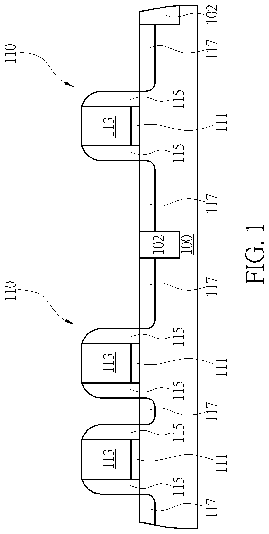
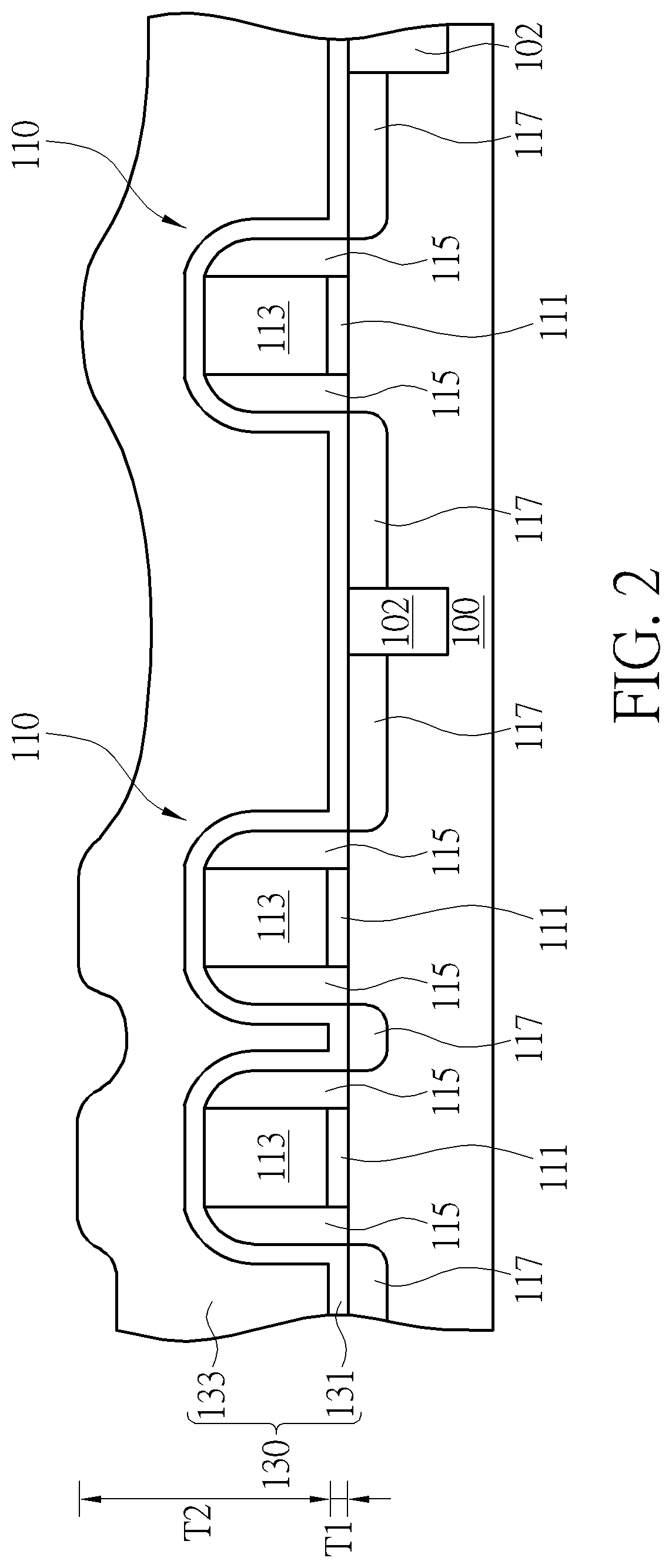
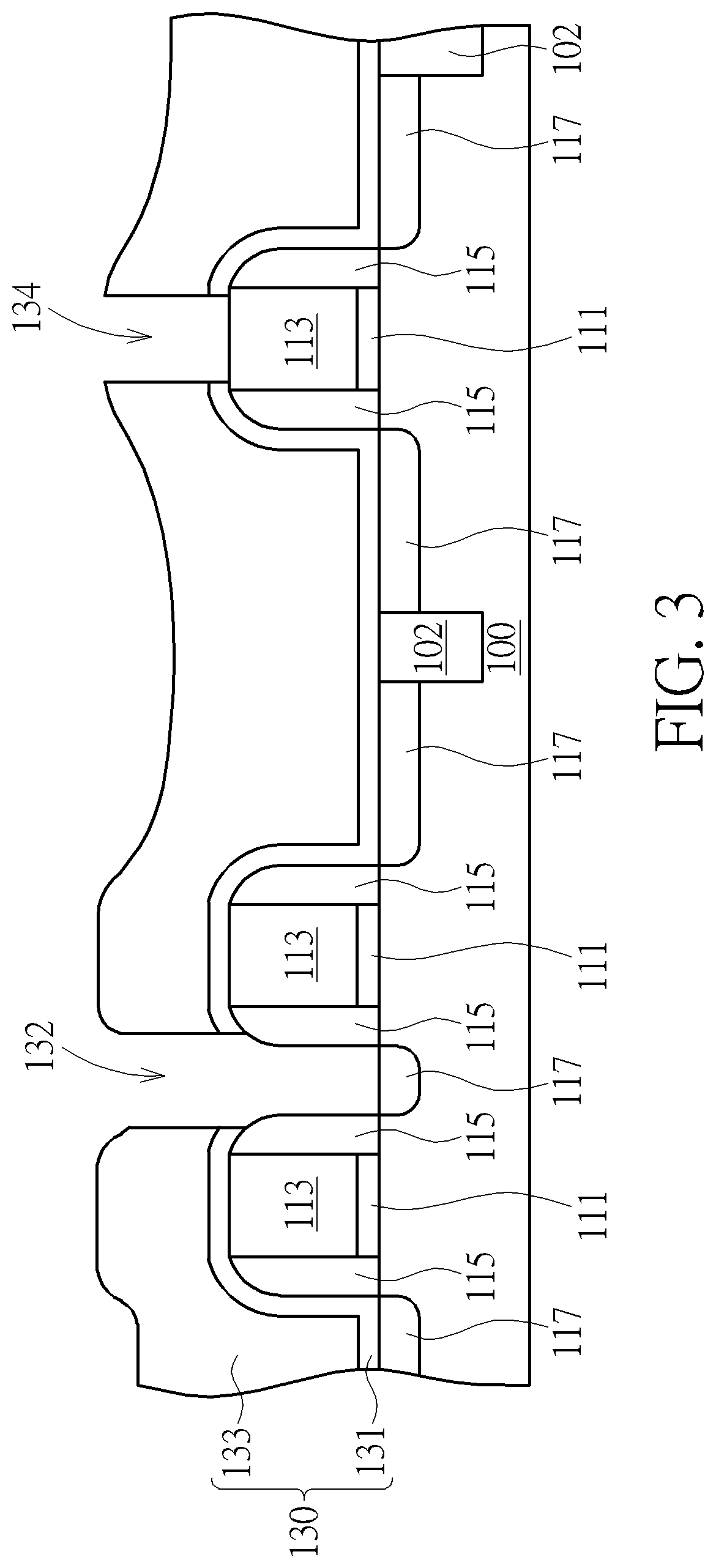
[0024]Referring to FIGS. 1-7, FIGS. 1-7 illustrate a method of forming a semiconductor device according to the first preferred embodiment of the present invention. Firstly, a substrate 100 such as a silicon substrate, an epitaxial silicon substrate or a silicon-on-insulator (SOI) substrate is provided, and at least one gate structure 110 is formed on the substrate 100, for example three gate structures 110 parallel disposed on the substrate 100 as shown in FIG. 1. The three gate structures 110 are preferably disposed within different pitches, so that, a portion of the gate structures 110 is disposed within a relative smaller pitch (for example the gate structures as shown in a left side of FIG. 1) and another portion of the gate structures 110 is disp...


PUM

PropertyMeasurementUnit
shrinkageaaaaaaaaaa
heightsaaaaaaaaaa
cell sizeaaaaaaaaaa

Abstract

The present invention relates to a semiconductor device and a method of forming the same, the semiconductor device includes a substrate, a gate structure, an insulating stacked structure and a first conductive layer. The gate structure is disposed on the substrate, and the insulating stacked structure covers the gate structure and the substrate to define a first opening thereinto expose a portion of the gate structure and a portion of the substrate. The first conductive layer covers surfaces of the first opening to directly contact the portion of the substrate and the portion of the gate structure, with the first conductive layer including two outer extension wings on a top surface of the insulating stacked structure.

Description

CROSS REFERENCE TO RELATED APPLICATIONS[0001]This application is a Divisional of application Ser. No. 16 / 116,949 filed Aug. 30, 2018, and included herein by reference.BACKGROUND OF THE INVENTION1. Field of the Invention[0002]The present invention relates generally to a semiconductor device and a method of forming the same and more particularly, to a semiconductor device having a pre-plug conductive layer to configure as a portion of the interconnection system thereof, and a method of forming the same.2. Description of the Prior Art[0003]Semiconductor integrated circuits are one of the most important hardware bases in the modern information society. A key design point of the semiconductor industry is to increase integration of integrated circuits, and therefore to use the area of integrated circuits more efficiently. Generally speaking, integrated circuits having complex functions are made up of many standard cells, each with basic functions. However, it is found that valuable areas ...

Claims


Application Information

Patent Timeline
Patent Type & Authority Applications(United States)
IPC IPC(8): H01L21/768H01L27/088H01L29/40H01L21/8234H01L29/423
CPCH01L21/76895H01L21/76897H01L29/42364H01L21/823475H01L27/088H01L29/401H01L23/528H01L21/7685H01L2221/1073H01L29/78H01L29/6656H01L21/76885H01L21/76834
Inventor WAN, WEN-WUCHENG, TIEN-HSIANGCHUNG, KUN-HSUAN
Owner UNITED MICROELECTRONICS CORP
Learn More