
Image recording apparatus

Active Publication Date: 2014-10-02
SEIKO EPSON CORP
View PDF2 Cites 7 Cited by
  • Summary
  • Abstract
  • Description
  • Claims
  • Application Information

AI Technical Summary

Benefits of technology

The invention provides a technology to effectively address the problem of liquid attached to the nozzle forming surface being cured by the incidence of light in an image recording technology that emits light from an irradiator provided between each print head. The technology involves providing print heads at different positions in the transport direction of the recording medium, and an irradiator between the print heads. The print heads discharge liquids with different compositions and ease of removal during curing. The light emitted from the irradiator has directionality in a direction receding from the print head that discharges the liquid with higher content rate of polyfunctional monomer, which has greater bonding force when cured. This reduces the difficulty of removing the liquid with higher content rate of polyfunctional monomer. The print heads are also designed to emit light in a direction perpendicular to the nozzle forming surface of the print head that discharges the liquid with lower content rate of polyfunctional monomer, which has easier removal. This technology effectively suppresses problems caused by the incidence of light on the nozzle forming surface of the print heads.

Problems solved by technology

In such an image recording apparatus, because the print head and the irradiator are arranged lined up, a problem arises in which light is incident on a nozzle forming surface (discharge surface) of the print head, and liquid attached to the nozzle forming surface is cured, as indicated by JP-A-2004-338223.
If liquid attached to the nozzle forming surface is cured, there is concern of defects occurring in the image recording.
However, in an image recording apparatus that performs image recording by ejecting the liquid from a plurality of print heads lined up in the transport direction while transporting the recording medium in the transport direction, there is concern of the advantage according to the configuration in which the irradiator is inclined being insufficiently utilized.
As a result, the liquid attached to the nozzle forming surface of the print head on the other side is cured to a corresponding extent, and for example, a situation may occur in which the liquid is not easily removed by the maintenance such as wiping.
Therefore, in a case in which the liquid with a higher content rate of polyfunctional monomer is attached to the nozzle forming surface and cured, the removal thereof has a tendency to be difficult.
However, because the print head discharges a liquid that is comparatively easy to remove during curing, the occurrence of problems caused by the incidence of light on the nozzle forming surface is effectively suppressed by appropriately performing maintenance, such as wiping.

Method used


Image

  • Image recording apparatus
  • Image recording apparatus
  • Image recording apparatus

Examples


Embodiment Construction

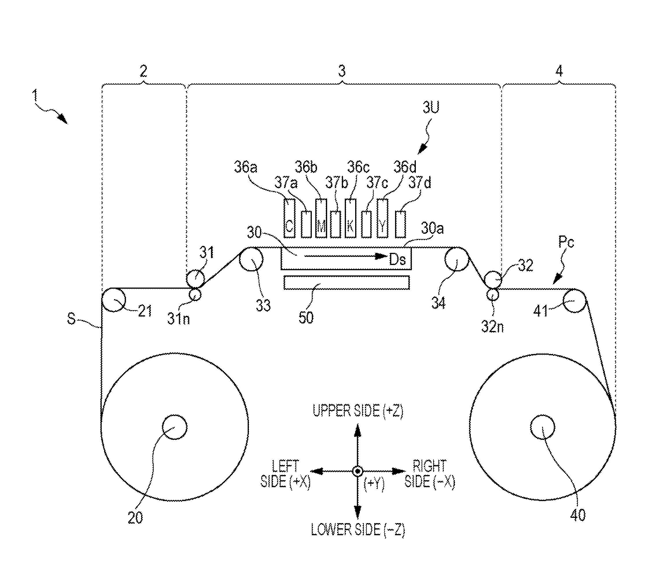
[0028]Below, embodiments of the image recording apparatus according to the invention will be described with reference to the drawings. FIG. 1 is a front view schematically showing an embodiment of an image recording apparatus to which the invention is applicable. In FIG. 1 or later drawings, in order to clarify the placement relationship of each portion of the apparatus, a three-dimensional Cartesian coordinate system which corresponds to the left to right direction X, the front to rear direction Y, and the vertical direction Z of the image recording apparatus 1 is adopted as necessary.

[0029]As shown in FIG. 1, in the image recording apparatus 1, a feeding portion 2, a processing portion 3, and a winding portion 4 are arranged in the left to right direction. The feeding portion 2 and the winding portion 4 have a feeding shaft 20 and a winding shaft 40 respectively. Both ends of a sheet S (web) are wrapped around the feeding portion 2 and the winding portion 4 to have a roll shape an...


PUM


Abstract

An image recording apparatus includes a first print head that discharges a first liquid that is cured through irradiation of light from a nozzle towards the recording medium; a second print head that discharges a second liquid in which a content rate of a tri-functional or higher polyfunctional monomer is different from that of the first liquid and that is cured through irradiation of light from a nozzle towards the recording medium, and is provided at a different position in the transport direction from the first print head; and an irradiator that irradiates the recording medium with light, and is arranged between the print heads in the transport direction, in which the irradiator emits light having directionality in a direction receding in the transport direction from a print head that discharges a liquid with a higher content rate from the print heads.

Description

BACKGROUND[0001]1. Technical Field[0002]The present invention relates to a technology in which an irradiator that irradiates a liquid with light by which the liquid is cured in an image recording technology in which a plurality of print heads that discharge a photocurable liquid are used.[0003]2. Related Art[0004]Image recording apparatuses, such as an ink jet printer, that perform image recording by discharging a photocurable liquid from the nozzles of a print head, and curing the liquid discharged onto the recording medium through light from an irradiator are known in the related art. In such an image recording apparatus, because the print head and the irradiator are arranged lined up, a problem arises in which light is incident on a nozzle forming surface (discharge surface) of the print head, and liquid attached to the nozzle forming surface is cured, as indicated by JP-A-2004-338223. If liquid attached to the nozzle forming surface is cured, there is concern of defects occurrin...

Claims


Application Information

Patent Timeline
IPC IPC(8): B41J11/00
CPCB41J11/002B41J3/543B41J11/00214
Inventor HAYASHI, YOSHIMITSUHORI, KAZUHITO
Owner SEIKO EPSON CORP
Learn More