
Headlight device for motorcycle

Inactive Publication Date: 2014-10-02
HONDA MOTOR CO LTD
View PDF6 Cites 8 Cited by
  • Summary
  • Abstract
  • Description
  • Claims
  • Application Information

AI Technical Summary

Benefits of technology

The present invention is about a motorcycle headlight device with LED light sources. The invention arranges the LED light sources on the upper surfaces of reflectors that are formed stepwise along the leftward and rightward directions of the motorcycle. This efficient arrangement of the substrates with LED light sources enhances external appearance quality while securing required functions like light distribution characteristics. The LED light sources are also located on the bottom surfaces of the reflectors, facing the curved bottom surfaces, which further improves external appearance quality. The LED light sources can be covered with the reflectors, preventing them from being visible in a front view. The invention also utilizes the dead spaces on the upper side of the reflectors to enhance cooling efficiency. Overall, the invention improves both external appearance quality and cooling efficiency.

Problems solved by technology

If the configuration of the tail lamp device as above-mentioned is applied to a headlight device having a plurality of light sources, particularly a headlight device appearing like eyes that are turned up at the corners, the following problems would be brought about.
Therefore, if the configuration of the tail lamp device as above-mentioned is applied to a headlight device shaped like eyes that are turned up at the corners, it would be difficult to efficiently arrange substrates with LED light sources mounted thereon, while securing such required functions as external appearance quality, light distribution characteristics, etc.

Method used


Image

  • Headlight device for motorcycle
  • Headlight device for motorcycle
  • Headlight device for motorcycle

Examples


Embodiment Construction

[0037]A headlight device for a motorcycle according to the present invention will be described in detail below, by showing a preferred embodiment and while referring to the accompanying drawings.

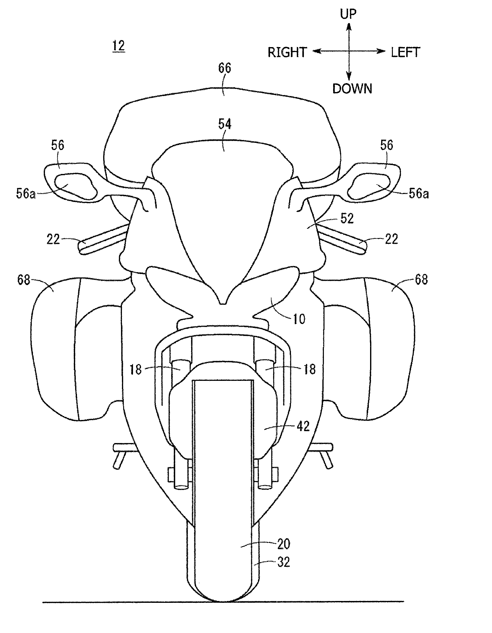
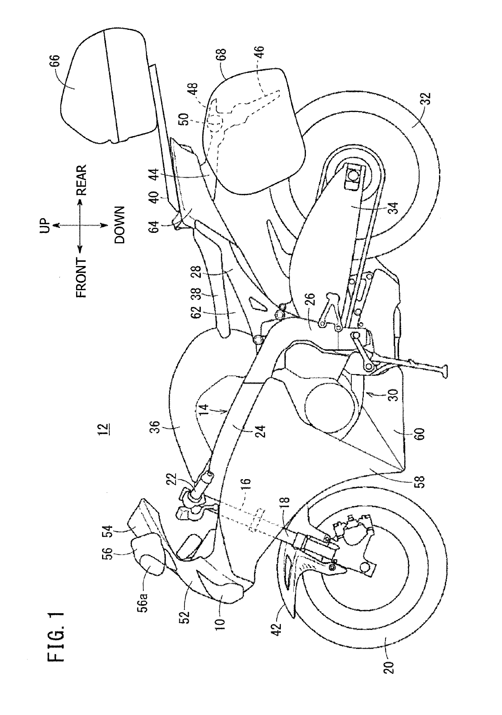
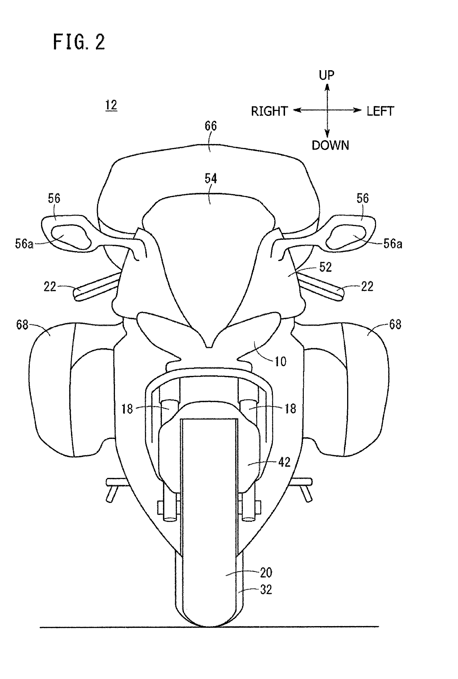
[0038]FIG. 1 is a left side view of a motorcycle 12 having mounted thereon a headlight device 10 according to this embodiment, and FIG. 2 is a front view of the motorcycle 12. The front, rear, up, down, left and right directions will be described in accordance with the directions of arrows shown in FIGS. 1 and 2, unless specified otherwise.

[0039]The motorcycle 12 has a body frame 14 with a head pipe 16 provided at a front end portion of the body frame 14. A pair of left and right front forks 18 are rotatably supported on the head pipe 16. The pair of left and right front forks 18 rotatably support a steering front wheel 20. A bar-shaped steerable handle 22 is mounted to upper portions of the pair of left and right front forks 18.

[0040]In addition, the body frame 14 further includes a pair of...


PUM


Abstract

A headlight device for a motorcycle that enables substrates with LED light sources mounted thereon to be disposed efficiently while securing such required functions as the external appearance quality of a shape like eyes that are turned up at the corners, light distribution characteristics, etc. In the headlight device for the motorcycle, a plurality of reflectors provided correspondingly to a plurality of substrates having headlight light sources mounted thereon are disposed in such shapes so as to be turned up, like eyes that are turned up at the corners, in a direction away from a center line in an external view. Each of upper surface parts of the reflectors is substantially horizontal and is in a stepped form relative to the adjacent upper surface part. The substrates are disposed substantially horizontally at the upper surface parts.

Description

CROSS-REFERENCE TO RELATED APPLICATIONS[0001]The present application claims priority under 35 USC 119 to Japanese Patent Application No. 2013-075374 filed Mar. 29, 2013 the entire contents of which are hereby incorporated by reference.BACKGROUND OF THE INVENTION[0002]1. Field of the Invention[0003]The present invention relates to a headlight device for a motorcycle, for reflecting light from a light source by a reflector and transmitting the reflected light through a lens to radiate the light forward.[0004]2. Description of Background Art[0005]PCT Patent Publication No. WO2009 / 110080 discloses a configuration in which a substrate with an LED light source thereon is disposed substantially horizontally inside a tail lamp device.[0006]In the above-mentioned configuration, on an upper surface and a bottom surface of a single sheet of substrate, a plurality of LED light sources are disposed along the longitudinal direction of the vehicle. In this case, light beams from the LED light sour...

Claims


Application Information

Patent Timeline
IPC IPC(8): F21S8/10B62J6/02
CPCF21S48/115F21S48/1317B62J6/02B60Q1/0683F21S41/192F21S41/55F21S43/14F21S43/27F21S43/239F21S43/245F21S43/247F21S45/33B62J6/026
Inventor OTSUJI, MIKUOHASHI, HAYATO
Owner HONDA MOTOR CO LTD
Learn More