
Lens barrel and imaging device

Active Publication Date: 2013-02-21
PANASONIC CORP
View PDF1 Cites 13 Cited by
  • Summary
  • Abstract
  • Description
  • Claims
  • Application Information

AI Technical Summary

Benefits of technology

The technology described in this patent makes lens barrels and imaging devices more compact. By placing the gear component in the middle of the main body component, a space between the gear and the first frame is created, which allows for more efficient use of this space. This leads to a smaller drive actuator and a more compact lens barrel.

Problems solved by technology

However, the actuator is usually disposed near the end of the support frame, so if a gear is formed at the base of the support frame, the actuator and the gear will tend to interfere with each other.
Therefore, with a lens barrel having a structure such as this, the layout of the members ends up being less efficient and the product more bulky because of the need to avoid interference between the actuator and the gear.

Method used


Image

  • Lens barrel and imaging device
  • Lens barrel and imaging device
  • Lens barrel and imaging device

Examples


first embodiment

[0037]Overview of Digital Camera

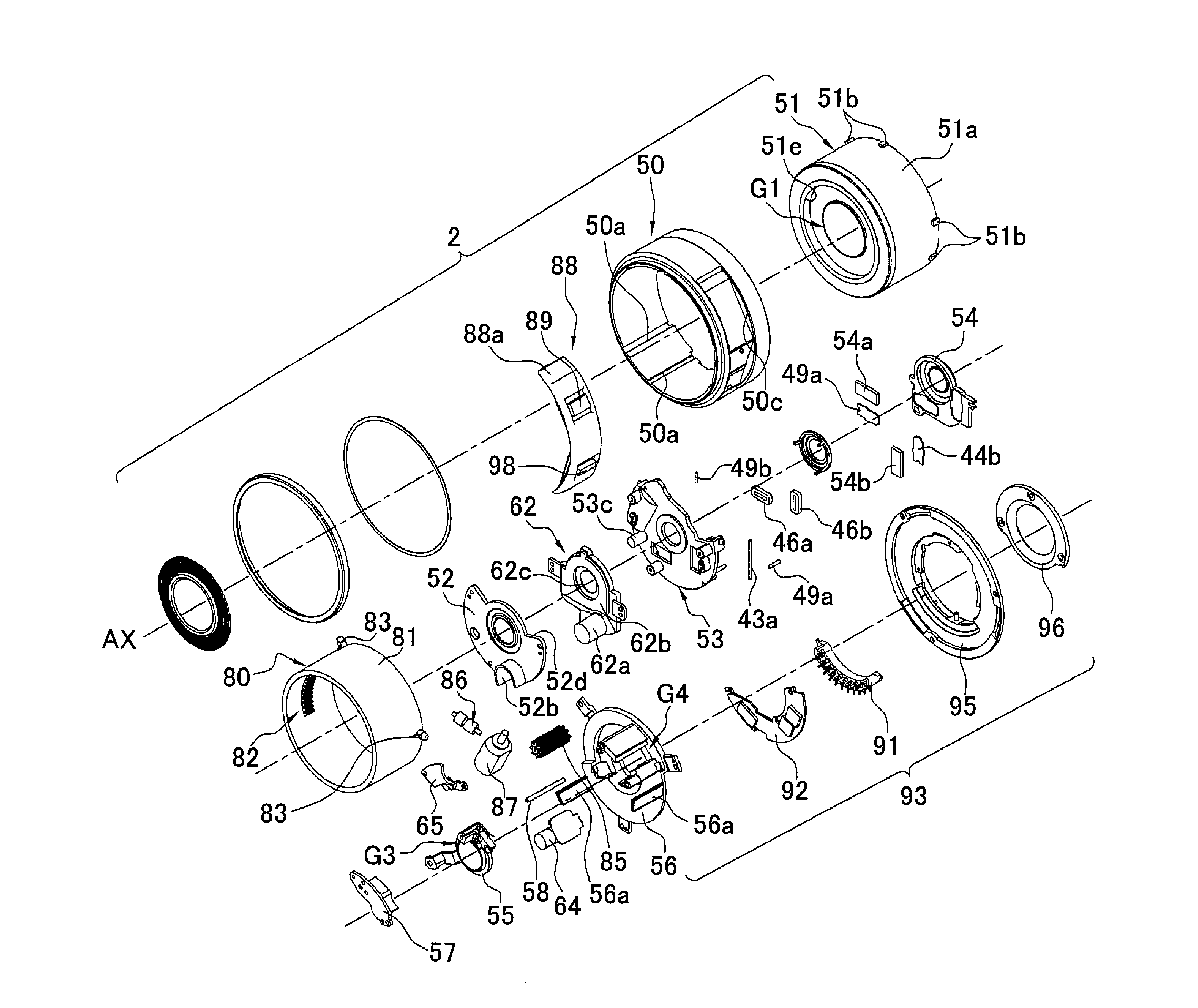
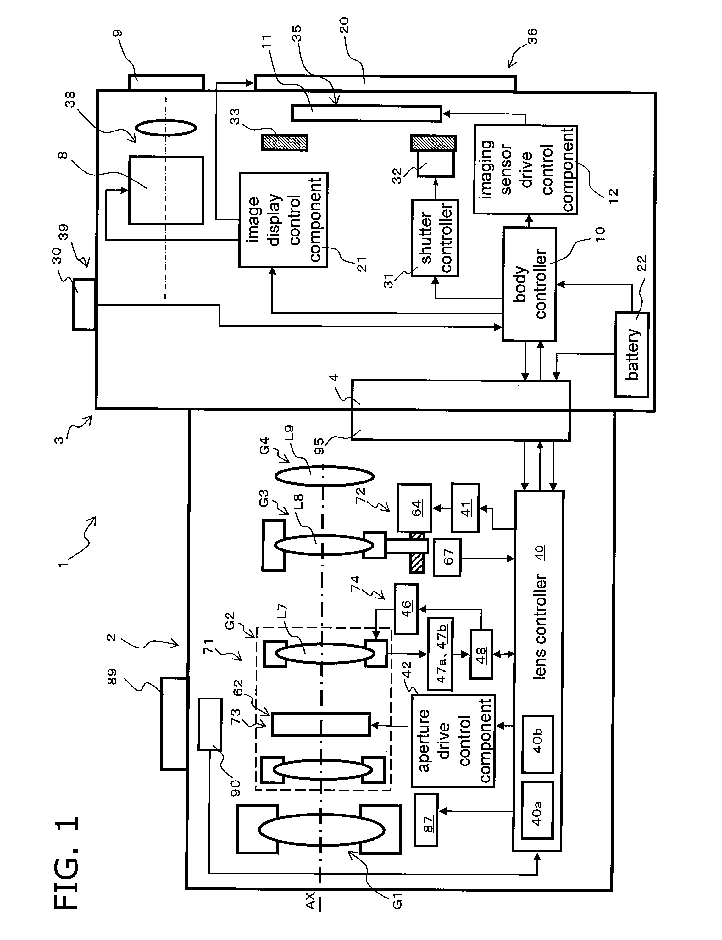
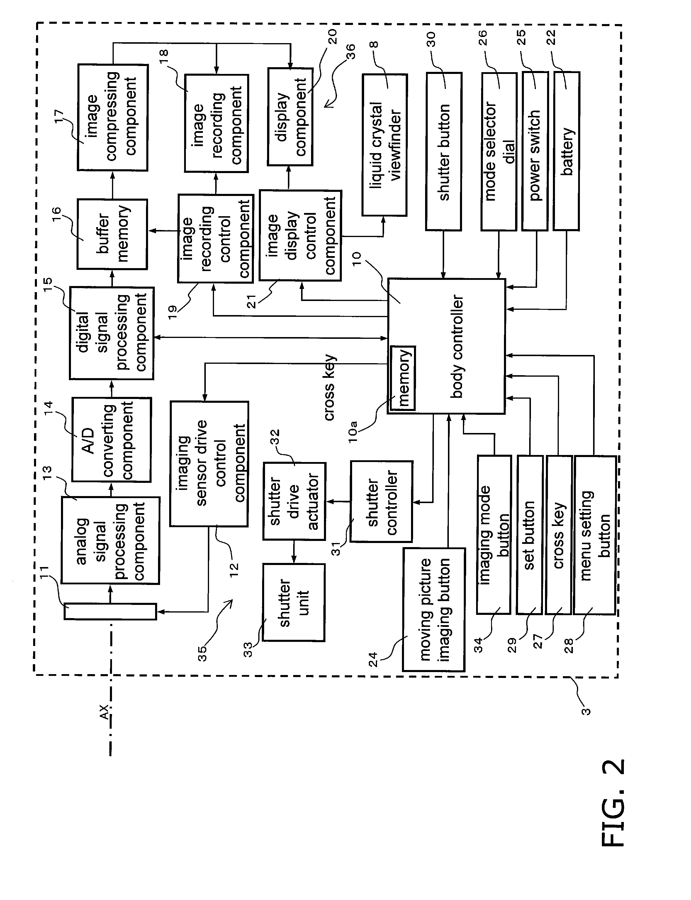
[0038]A digital camera 1 will be described through reference to FIGS. 1 to 3A and 3B. As shown in FIG. 1, the digital camera 1 (an example of an imaging device) is an interchangeable lens type of digital camera, and mainly comprises a camera body 3 (an example of a camera body) and an interchangeable lens unit 2 (an example of a lens barrel) that is removably mounted to the camera body 3. The interchangeable lens unit 2 is removably mounted to a body mount 4 provided to the front face of the camera body 3, via a lens mount 95.

[0039]This digital camera 1 is what is known as a mirror-less single-lens camera, in which no quick-return mirror is installed between the body mount 4 and an imaging sensor 11.

[0040]Simplified Configuration of Interchangeable Lens Unit

[0041]The simplified configuration of the interchangeable lens unit 2 will be described through reference to FIG. 1 and FIGS. 4 to 7. As shown in FIG. 1, the interchangeable lens unit 2 has an opti...

second embodiment

[0228]In the first embodiment given above, the zoom lever 89 and the focus lever 98 are used to change the focal distance and adjust the focus. However, changing the focal distance may be accomplished using a zoom ring, and focusing may be accomplished using a focus ring. An interchangeable lens unit 302 pertaining to a second embodiment will now be described, using a zoom ring as an example.

[0229]Those components that have substantially the same function as those in the first embodiment above will be numbered the same and will not be described in detail again.

[0230]The interchangeable lens unit 302 shown in FIG. 21 is equipped with a zoom ring unit 388. The zoom ring unit 388 has a stop ring 388a (an example of a restricting member) and a zoom ring 389 (an example of an interface member). In other words, the stop ring 388a is an annular member, and is mounted to the end of a fixed frame 350 on the subject side. The stop ring 388a is disposed on the opposite side of the fixed frame ...


PUM


Abstract

An interchangeable lens unit comprises a lens housing, a cam frame, and a zoom drive unit. The zoom drive unit is mounted to the lens housing, and rotationally drives the cam frame with respect to the lens housing. The lens housing has a substantially cylindrical main body component and a gear component that is disposed on the inner peripheral face of the main body component and to which the drive force of the zoom drive unit is transmitted. The gear component is disposed substantially in the middle of the main body component in the optical axis direction.

Description

BACKGROUND[0001]1. Technical Field[0002]The technology disclosed herein relates to a lens barrel used in an imaging device.[0003]2. Background Information[0004]Imaging devices that produce image data about a subject have been rapidly growing in popularity in recent years. A lens barrel for adjusting the focal distance is installed in an imaging device. Known imaging devices include, for example, integrated types of cameras and those with an interchangeable lens. Integrated cameras have the lens barrel built in. An interchangeable lens camera has a camera body and an interchangeable lens unit that is mountable to and removable from the camera body. For example, the lens barrel in this case is built into the interchangeable lens unit.SUMMARY[0005]An actuator is built into this type of lens barrel. Examples of actuators include a zoom motor used to adjust the focal distance, and a focus motor used to focus on the desired main subject.[0006]These actuators transmit torque through a gear...

Claims


Application Information

Patent Timeline
IPC IPC(8): G02B7/04
CPCG02B7/102
Inventor ITO, DAISUKE
Owner PANASONIC CORP
Learn More