Vehicle lamp

a technology for vehicles and lamps, applied in the direction of transportation and packaging, fixed installation, light and heating equipment, etc., can solve the problem of difficulty in visibly recognizing

Active Publication Date: 2014-10-02
KOITO MFG CO LTD
View PDF22 Cites 2 Cited by
  • Summary
  • Abstract
  • Description
  • Claims
  • Application Information

AI Technical Summary

Benefits of technology

[0006]In the projector-type vehicle lamp provided with the mirror member, the upward reflecting surface of the mirror member has a front edge which is formed to pass through a rear focus of a projection lens or the vicinity thereof. Here, when the front edge is formed to extend along a meridional image surface of the projection lens, a cut-off line may be clearly formed. This may eliminate the possibility of giving a glare to a driver of an oncoming vehicle or a preceding vehicle.
[0008]The present disclosure has been made in consideration of these problems, and an object of the present disclosure is to provide a projector-type vehicle lamp which may enhance visibility of, for example, a pedestrian at the roadside without giving a glare to a driver of an oncoming vehicle or a preceding vehicle.

Problems solved by technology

However, there is a problem in that when the cut-off line is too clear, it becomes difficult to visibly recognize, for example, a pedestrian present at the roadside.

Method used


Image

  • Vehicle lamp
  • Vehicle lamp
  • Vehicle lamp

Examples


Embodiment Construction

[0020]In the following detailed description, reference is made to the accompanying drawing, which form a part hereof. The illustrative embodiments described in the detailed description, drawing, and claims are not meant to be limiting. Other embodiments may be utilized, and other changes may be made, without departing from the spirit or scope of the subject matter presented here.

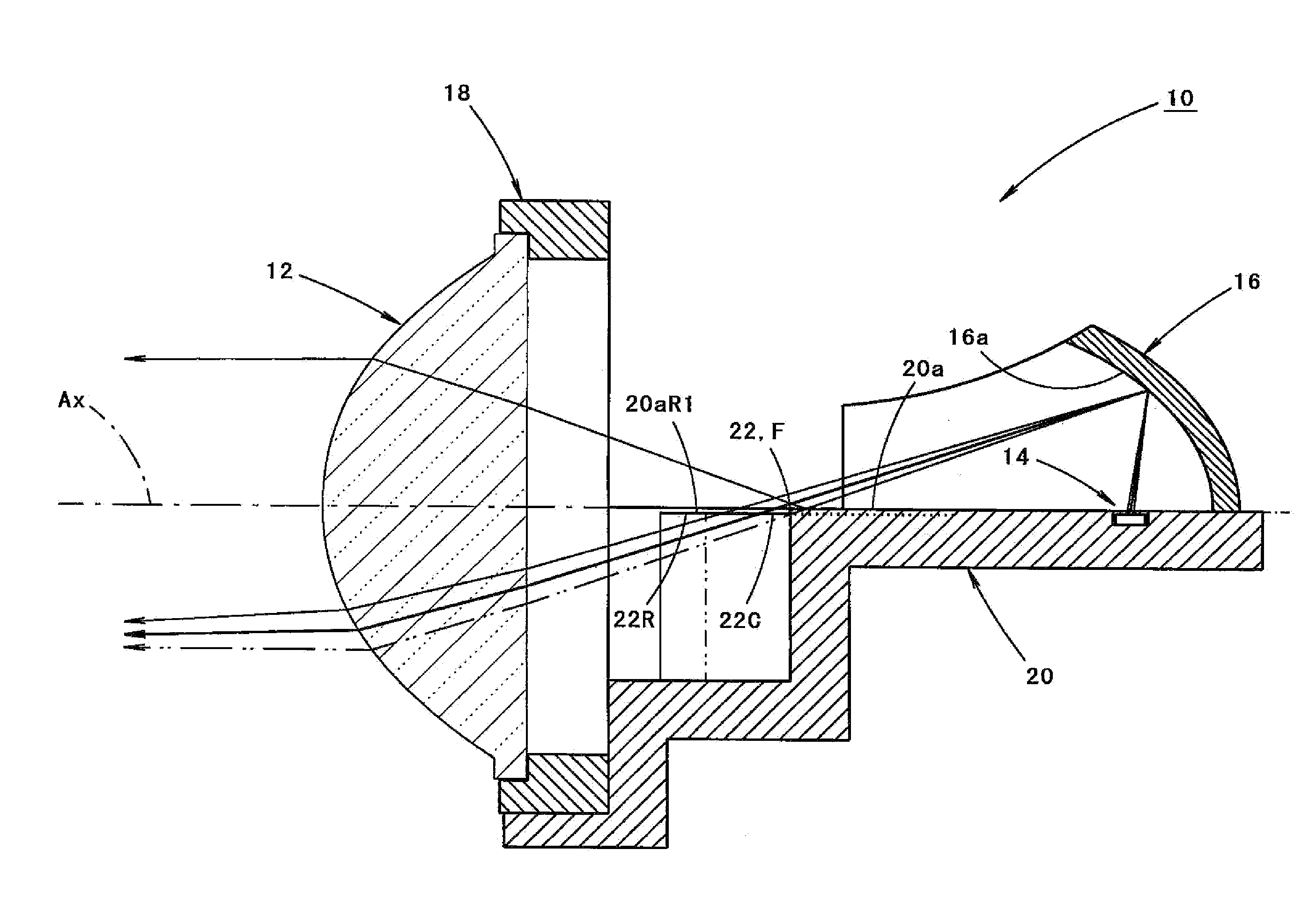
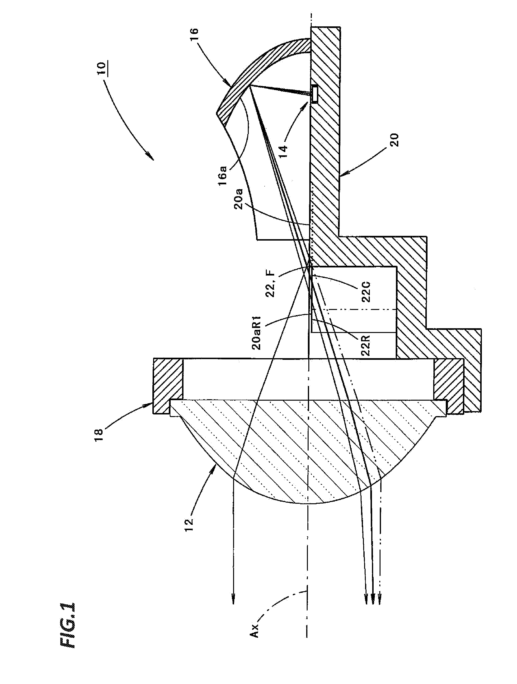
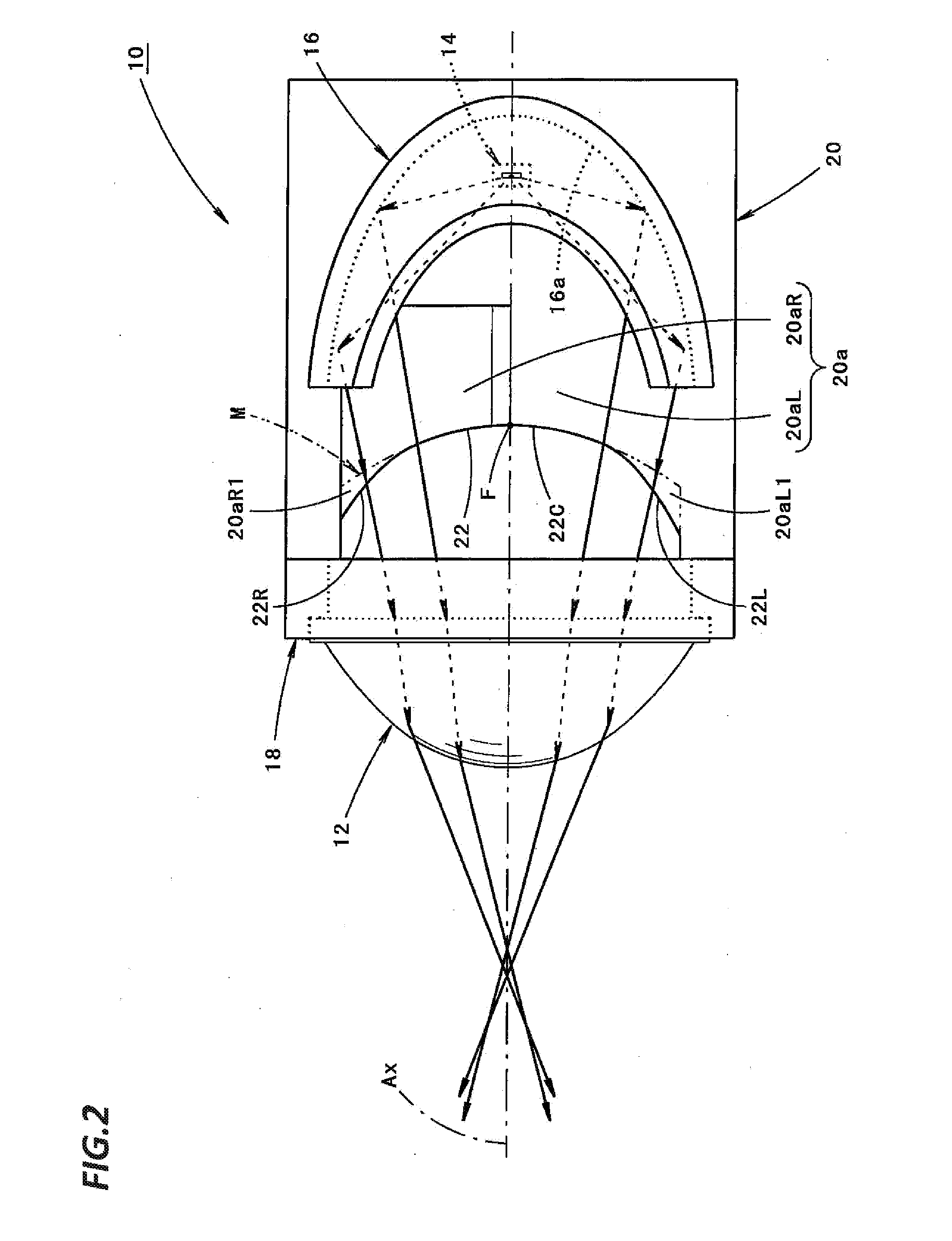
[0021]The kind of “the light source” is not particularly limited. Also, as long as “the light source” is disposed at the rear side of the rear focus of the projection lens, for example, a specific position or direction of the light source is not particularly limited.

[0022]As long as “the front edge of the upward reflecting surface” in “the mirror member” is disposed to pass through the rear focus of the projection lens or the vicinity thereof, for example, a specific formation range or surface shape of “the upward reflecting surface” is not particularly limited.

[0023]There is no specific limitation in specif...


PUM


Abstract

Disclosed is a projector-type vehicle lamp. The vehicle lamp includes a mirror member which has an upward reflecting surface that upwardly reflects a part of the light reflected from a reflector. A front edge of the upward reflecting surface passes through a rear focus F of a projection lens. A central portion of a front edge of the upward reflecting surface is formed to extend along a meridional image surface of the projection lens, and left and right end portions of the front edge are formed to be displaced forward from the meridional image surface. Accordingly, a central portion of a cut-off line of a low-beam light distribution pattern is formed to be clear and left and right end portions of the cut-off line become blurred such that light may be irradiated to a space in the upper vicinity of the left end portion and / or the right end portion.

Description

CROSS-REFERENCE TO RELATED APPLICATIONS[0001]This application is based on and claims priority from Japanese Patent Application No. 2013-075634, filed on Apr. 1, 2013, with the Japan Patent Office, the disclosure of which is incorporated herein in its entirety by reference.TECHNICAL FIELD[0002]The present disclosure relates to a projector-type vehicle lamp, and particularly to a projector-type vehicle lamp provided with a mirror member.BACKGROUND[0003]In general, a projector-type vehicle lamp is configured to reflect light from a light source disposed at the rear side of a rear focus of a projection lens toward a projection lens by a reflector.[0004]When a light distribution pattern having a cut-off line at the upper end thereof such as, for example, a low-beam light distribution pattern, is formed by the above described vehicle lamp, a configuration provided with a shade for shielding a part of the light reflected from the reflector is frequently employed.[0005]For example, Japanese...

Claims


Application Information

Patent Timeline
Patent Type & Authority Applications(United States)
IPC IPC(8): F21S8/10F21W107/10
CPCF21S48/125F21S41/255F21S41/321F21S41/43F21S41/365F21S41/148
Inventor NAKADA, YUSUKE
Owner KOITO MFG CO LTD
Why Eureka
Try Eureka