LED display device and method for correcting luminance thereof

A brightness correction and display device technology, applied to static indicators, instruments, electrical components, etc., can solve the problems of different brightness reduction rates, brightness reduction, brightness fluctuations, etc., achieve stable and uniform brightness, maintain brightness uniformity and color The effect of uniformity

Inactive Publication Date: 2019-11-15
MITSUBISHI ELECTRIC CORP
View PDF2 Cites 1 Cited by
  • Summary
  • Abstract
  • Description
  • Claims
  • Application Information

AI Technical Summary

Problems solved by technology

However, since the brightness of LEDs decreases as the lighting time becomes longer, the brightness reduction rate of each LED varies depending on the content of the image, and as a result, brightness fluctuations and color fluctuations occur for each pixel.

Method used


Image

  • LED display device and method for correcting luminance thereof
  • LED display device and method for correcting luminance thereof
  • LED display device and method for correcting luminance thereof

Examples


Embodiment approach 1

[0032]

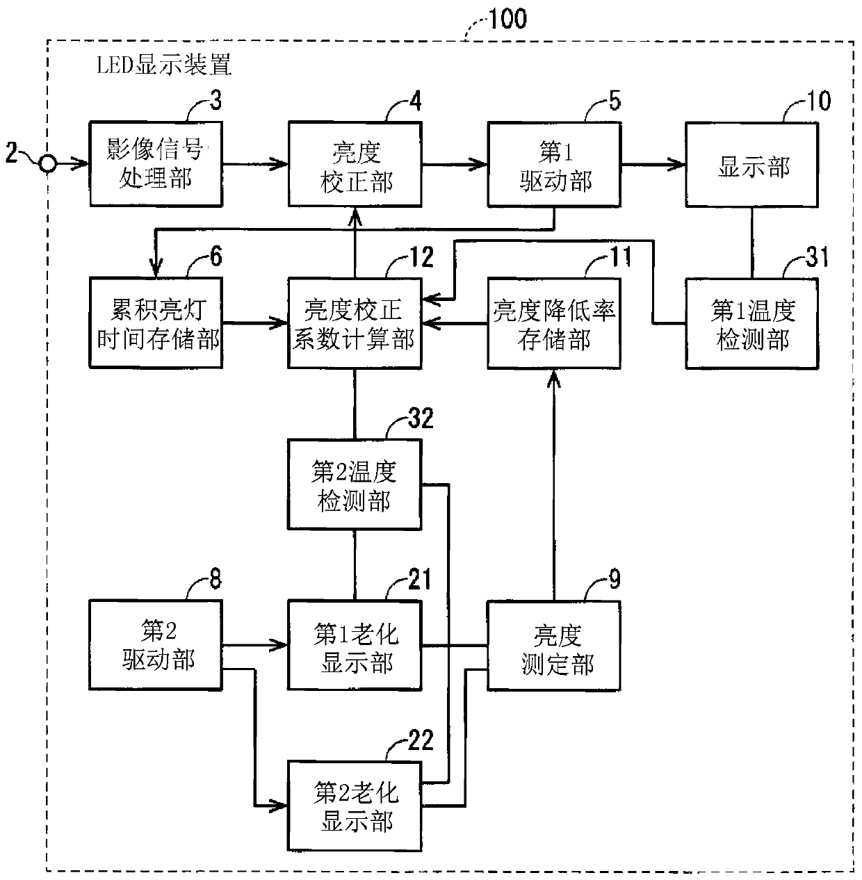
[0033] figure 1 It is a functional block diagram of the LED display device 100 in the first embodiment. also, figure 2 It is a more detailed block diagram of the periphery of the display unit 10 . image 3 It is a more detailed block diagram of the periphery of the first aging display unit 21 and the second aging display unit 22 .

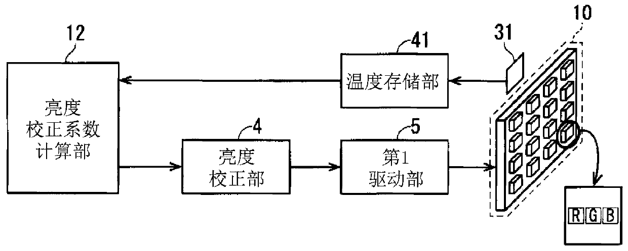
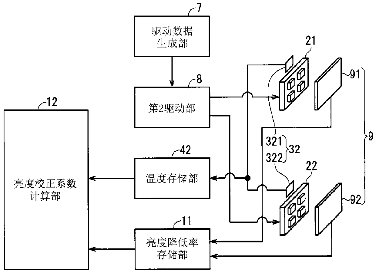
[0034] Such as figure 1 As shown, the LED display device 100 includes a display unit 10, a first drive unit 5, a first temperature detection unit 31, a first aging display unit 21, a second aging display unit 22, a second drive unit 8, a brightness measurement unit 9, The second temperature detection unit 32 , the luminance reduction rate storage unit 11 , the accumulated lighting time storage unit 6 , the luminance correction coefficient calculation unit 12 , and the luminance correction unit 4 .

[0035] The display module included in the display unit 10 includes a plurality of unit pixels arranged in a matrix of M rows and N colu...

Embodiment approach 2

[0139] Figure 12 It is a graph showing the luminance reduction rate when the green LED element is driven with different duty ratios. Such as Figure 12 As shown, the greater the duty cycle, the greater the brightness reduction rate.

[0140] In Embodiment 1, the measurement LED element is driven at the same duty ratio as the maximum duty ratio in the display unit 10 . In Embodiment 2, each of the first aging display unit 21 and the second aging display unit 22 includes a plurality of measurement LED elements, and the respective LED elements are driven at different duty ratios. For example, if Figure 12 As shown, a plurality of measurement LED elements are driven at duty ratios of 100%, 75%, 50%, and 25%, respectively.

[0141] For example, assuming that the maximum cumulative lighting time tgmax of the green LED element is 50K, in the luminance reduction rate storage unit 11, the green measurement LED element stores Figure 12 The brightness reduction rate shown. In th...

Embodiment approach 3

[0147] Figure 13 It is a detailed block diagram around the display unit 10 of the LED display device 100 in the third embodiment. In Embodiment 1, the display unit 10 is configured to include one display module. On the other hand, in Embodiment 3, if Figure 13 As shown, the display unit 10 is configured to include a plurality of display modules. Combine multiple display modules to form one screen.

[0148] In Embodiment 3, the first drive unit 5 selects an area corresponding to each display module based on the video signal input from the brightness correction unit 4, and drives each display module. A plurality of display modules are connected, for example, in a daisy chain. In addition, the first temperature detection unit 31 individually detects the temperature of a plurality of LED elements included in each display module.

[0149] In Embodiment 1, it is the following structure: the display part 10 is provided with one display module, such as figure 1 As shown, the d...


PUM


Abstract

The purpose of the present invention is to provide an LED display device and a method for correcting the luminance of the LED display capable of correcting the luminance of each LED element to therebysuppress the degradation of image quality due to the variation in the characteristics of each LED element. An LED display device (100) comprises: a display unit (10) including a display module composed of a plurality of LED elements; a first temperature detector (31); a first and a second aging display unit (21, 22) equipped with at least one measurement LED element that is equivalent to the LEDelement; a luminance measurement unit (9) for measuring the luminance of the measurement LED element; a second temperature detector (32); a cumulative lighting time storage unit (6) for storing the cumulative lighting time of the plurality of LED elements; a luminance reduction rate storage unit (11) for storing the relationship between the cumulative lighting time of the measurement LED element and the luminance reduction rate of the measurement LED element; and a luminance correction factor calculation unit (12) for calculating the luminance correction factors for the plurality of LED elements. The luminance correction factor calculation unit (12) corrects luminance correction factors on the basis of the temperatures detected by first and second aging display unit (21, 22).

Description

technical field [0001] The present invention relates to an LED device and its brightness correction method, and more particularly to an LED display device and its brightness correction method for displaying image information by controlling blinking of a plurality of LEDs (Light Emitting Diodes: Light Emitting Diodes) arranged in a matrix. Background technique [0002] Display devices using LEDs have been widely used for outdoor and indoor advertising displays and the like through technological development and cost reduction of LEDs. These LED display devices are mainly dynamic image displays of natural paintings and animations at present. In recent years, with the narrowing of the pixel pitch, the viewing distance has become shorter, and thus it has been used in conference rooms, monitoring purposes, and the like. Especially in surveillance applications, personal computer images that are close to still images are often displayed. However, since LEDs decrease in luminance a...

Claims


Application Information

Patent Timeline
Patent Type & Authority Applications(China)
IPC IPC(8): G09G3/32G09G3/20
CPCG09G3/2014G09G3/32G09G2300/0413G09G2320/0233G09G2320/029G09G2320/041G09G2320/045G09G2320/048G09G2360/145G09G3/20H01L33/00
Inventor 町田直之涉江重教浅村吉范
Owner MITSUBISHI ELECTRIC CORP
Why Eureka
Try Eureka