Neighborhood brightness matching for uniformity in a tiled display screen

a tiled display screen and neighborhood brightness technology, applied in the field of tiled display screens, can solve the problems of inability to prevent initial calibration and degrade the brightness of individual tiles, and achieve the effect of improving the overall brightness of the tiled display device, maximizing the overall brightness of the display device, and improving the uniformity and overall brightness of images

Inactive Publication Date: 2011-12-08
PRYSM INC
View PDF9 Cites 45 Cited by
  • Summary
  • Abstract
  • Description
  • Claims
  • Application Information

AI Technical Summary

Benefits of technology

[0007]One or more embodiments of the invention provide systems and methods for brightness matching between the individual tiles of a tiled display system for improved uniformity and overall brightness of images produced by the display system. Regions of the display system adjacent to a tile with low brightness performance are incremented in brightness from the brightness level of the low brightness tile to the brightness level of the higher brightness tiles. By incrementing the brightness of such regions according to embodiments of the invention, perceived brightness uniformity of images produced by the display system is maintained while maximizing the overall brightness of the tiled display device. The regions used to increment brightness may be as large as an entire tile or as small as a single pixel element.

Problems solved by technology

Because the human eye can readily perceive small differences in brightness uniformity of a displayed image, the use of multiple display devices in a tiled display system can produce visual artifacts in an image when the output of one or more of the individual tiles is not closely matched to the brightness of adjacent tiles.
However, because the brightness of individual tiles may degrade over time, for example due to changes in light source performance, initial calibration cannot prevent brightness nonuniformity of a tiled display system throughout the life of the system.

Method used


Image

  • Neighborhood brightness matching for uniformity in a tiled display screen
  • Neighborhood brightness matching for uniformity in a tiled display screen
  • Neighborhood brightness matching for uniformity in a tiled display screen

Examples


Embodiment Construction

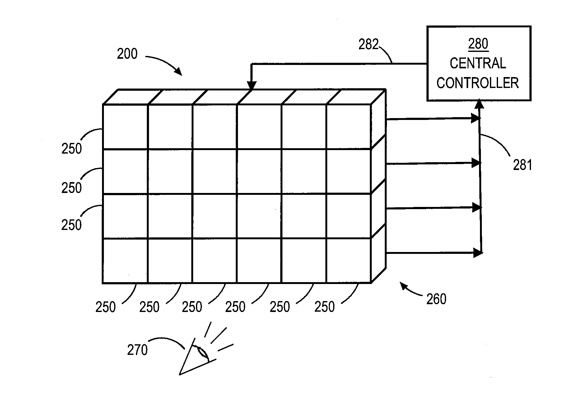
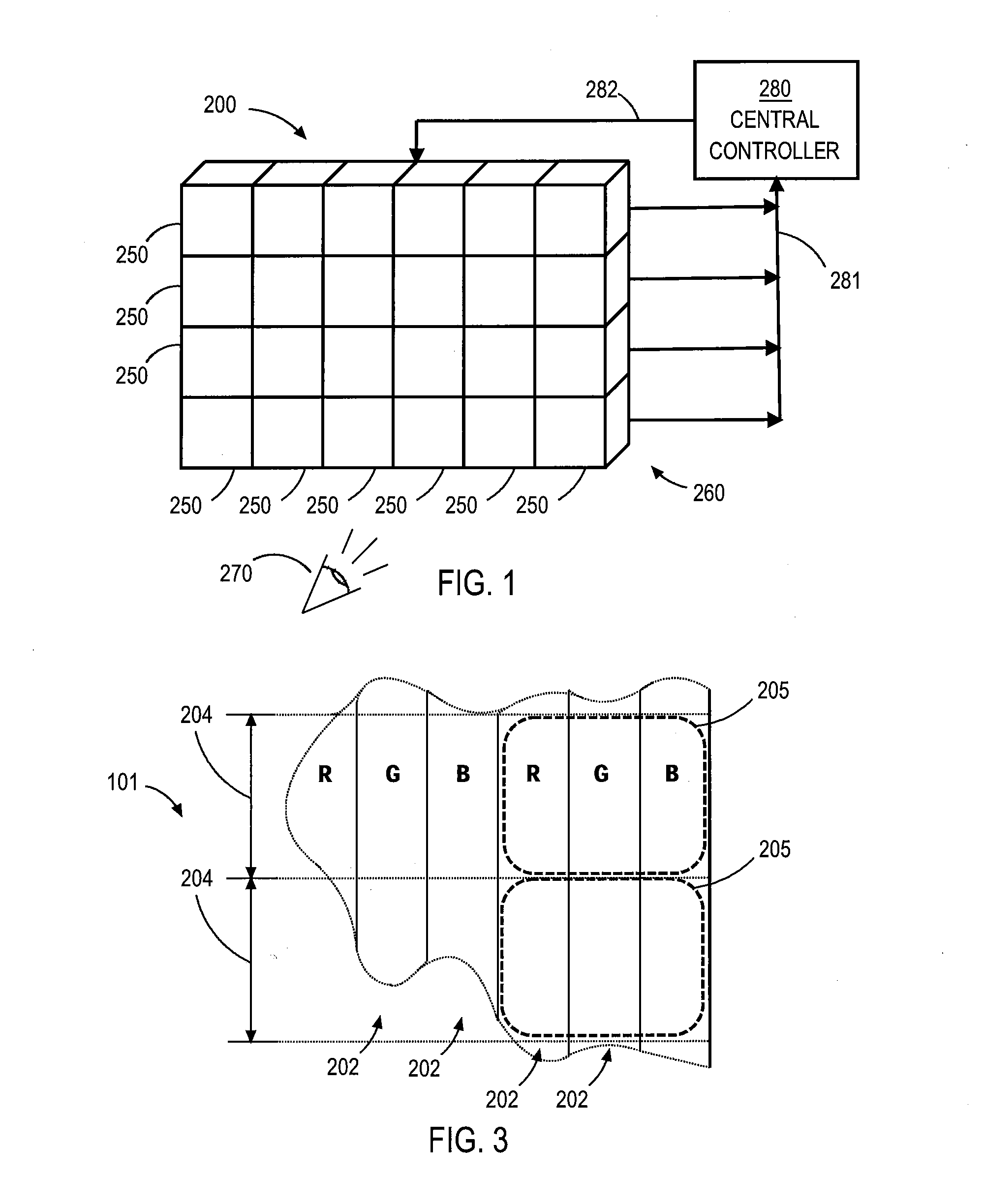
[0022]FIG. 1 is a perspective schematic diagram of a tiled display system 200 that may benefit from embodiments of the invention. Tiled display system 200 comprises a plurality of tiles 250, which are positioned to form a single display screen 260 for a viewer 270. Each of tiles 250 is a light-based electronic display device, such as a laser-phosphor display (LPD), a light-emitting diode (LED) digital light processing (DLP), or an LED-liquid crystal display (LCD) device, and is configured to operate in conjunction with the other tiles 250 to produce a single coherent image for viewer 270. Each of tiles 250 also includes a luminance detector (not shown in FIG. 1 for clarity) for dynamically monitoring the output intensity of the light source or light sources in the tile 250. Luminance is a photometric measure of the luminous intensity per unit area of light traveling in a given direction. Tiled display system 200 includes a central controller 280 configured to receive luminance data ...


PUM


Abstract

Brightness between the individual tiles of a tiled display system is matched for improved uniformity and overall brightness of images produced by the display system. Regions of the display system adjacent to a tile with low brightness performance are incremented in brightness from the brightness level of the low brightness tile to the brightness level of higher brightness tiles. By incrementing the brightness of such regions according to embodiments of the invention, perceived brightness uniformity of images produced by the tiled display system is maintained while maximizing the overall brightness of the display device. The regions used to increment brightness may be as large as an entire tile or as small as a single pixel element.

Description

BACKGROUND OF THE INVENTION[0001]1. Field of the Invention[0002]Embodiments of the present invention generally relate to tiled display screens, and more specifically, to systems and methods of brightness matching for improved uniformity and brightness of such display screens.[0003]2. Description of the Related Art[0004]Electronic display systems are commonly used to display information from computers and other sources. Typical display systems range in size from small displays used in mobile devices to very large displays, such as tiled displays, that are used to display images to thousands of viewers at one time. Tiled display systems are generally made up of multiple smaller individual display devices, or “tiles”, that are carefully aligned when assembled to provide a seamless and uniform appearance.[0005]Because the human eye can readily perceive small differences in brightness uniformity of a displayed image, the use of multiple display devices in a tiled display system can produ...

Claims


Application Information

Patent Timeline
Patent Type & Authority Applications(United States)
IPC IPC(8): G09G5/10G09G5/00
CPCG09G3/025G09G3/2003G09G2300/026G09F9/3026G09G2320/048G09G2360/14G09G2360/141G09G2320/0233
Inventor MAHAJAN, AMIT
Owner PRYSM INC
Why Eureka
Try Eureka