Vehicle headlamp

a headlamp and headlamp technology, applied in the field of headlamps, can solve the problems of increasing the possibility of rubbing between the first and second shades, and affecting the smooth operation of the light distribution pattern switching mechanism

Inactive Publication Date: 2012-05-15
KOITO MFG CO LTD
View PDF9 Cites 1 Cited by
  • Summary
  • Abstract
  • Description
  • Claims
  • Application Information

AI Technical Summary

Benefits of technology

[0011]One or more embodiments of the invention provide a vehicle headlamp in which an operation of shades is smooth.
[0014]Accordingly, a rubbing between the first shade and the second shade is prevented when the second shade moves, so that a smooth operation of the second shade can be secured.
[0015]According to a second aspect, the first shade may be formed in a curved shape in a manner that an amount of deviation of the first shade in the forward direction increases toward a side directions with reference to a portion of the first shade crossing the optical axis, and the light shielding portion of the second shade may be formed in a curved shape in a manner that one end portion of the light shielding portion locates in a vicinity of the rear side focal point and an amount of deviation of the light shielding portion in the forward direction increases toward the other end portion, when the second shade positions in the second position. Thus, the cut off line of the second light distribution pattern formed when the second shade positioned in the second position can be formed clearly.
[0016]In a third aspect, the light shielding portion of the second shade may include a flat plane portion opposed to the upper end of the first shade when the second shade positions in the second position. Thus, the rigidity of the second shade can be enhanced.
[0017]In a fourth aspect, the light shielding portion of the second shade may include a front side shielding portion that protrudes downward from a front edge of the flat plane portion and that covers the upper end of the first shade from the front side when the second shade positions in the second position. Thus, since a light passing through a slit between the flat plane portion and the upper end of the first shade is shielded, the occurrence of a glare light can be prevented.
[0018]In a fifth aspect, the upper end of the first shade may include a cut line forming portion that forms a cut line of the light distribution pattern, the cut line forming portion may include a first portion that forms a horizontal cut line on an opposite lane side and a second portion that forms a horizontal cut line on an own lane side, the flat plane portion of the second shade may be opposed to the first portion when the second shade positioned in the second position, and at least a part of the front side shielding portion of the second shade may extend to one end portion of the second portion on a side of the first portion. Thus, since a light passing through a slit between the upper end of the first shade and an opening edge of a relief notch is shielded, the occurrence of a glare light can be prevented.

Problems solved by technology

However, according to the vehicle headlamp disclosed in JP-A-2006-073224, since the first shade and the second shade are closely disposed in the front and rear direction of a vehicle, when the second shade is moved vertically, the first shade and the second shade may rub with each other so that the smoothing operation of the light distribution pattern switching mechanism may be impeded.
However, when it is intended to more clarify the cut line, the possibility of a rubbing between the first and second shades increases and so the smoothing operation of the light distribution pattern switching mechanism is more likely impeded.

Method used


Image

  • Vehicle headlamp
  • Vehicle headlamp
  • Vehicle headlamp

Examples


Embodiment Construction

[0028]Hereinafter, an exemplary embodiment of the invention is explained with reference to accompanying drawings.

[0029]Vehicle headlamps 1, 1 are attached to respective left and right end portions of a front end portion of a vehicle body.

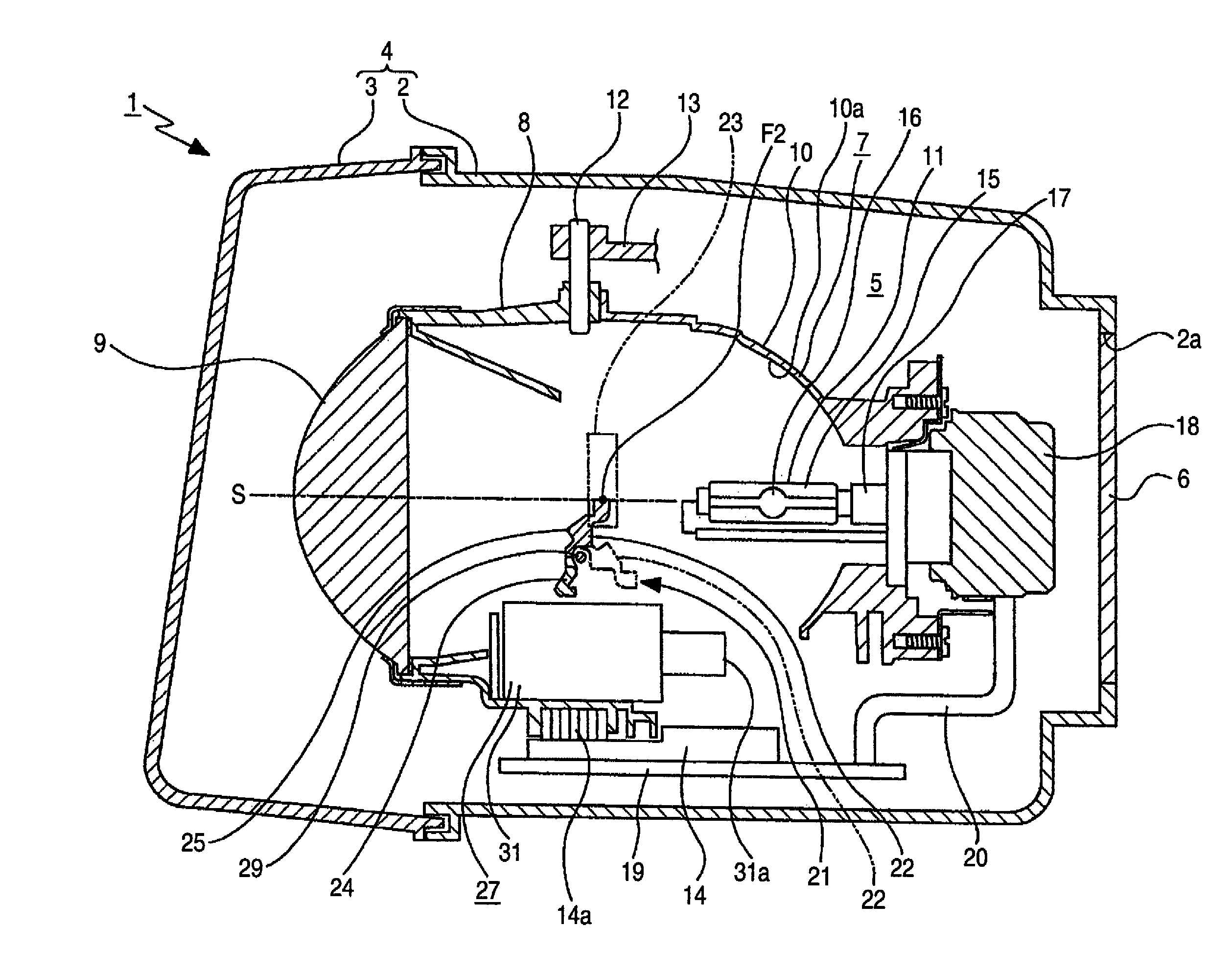
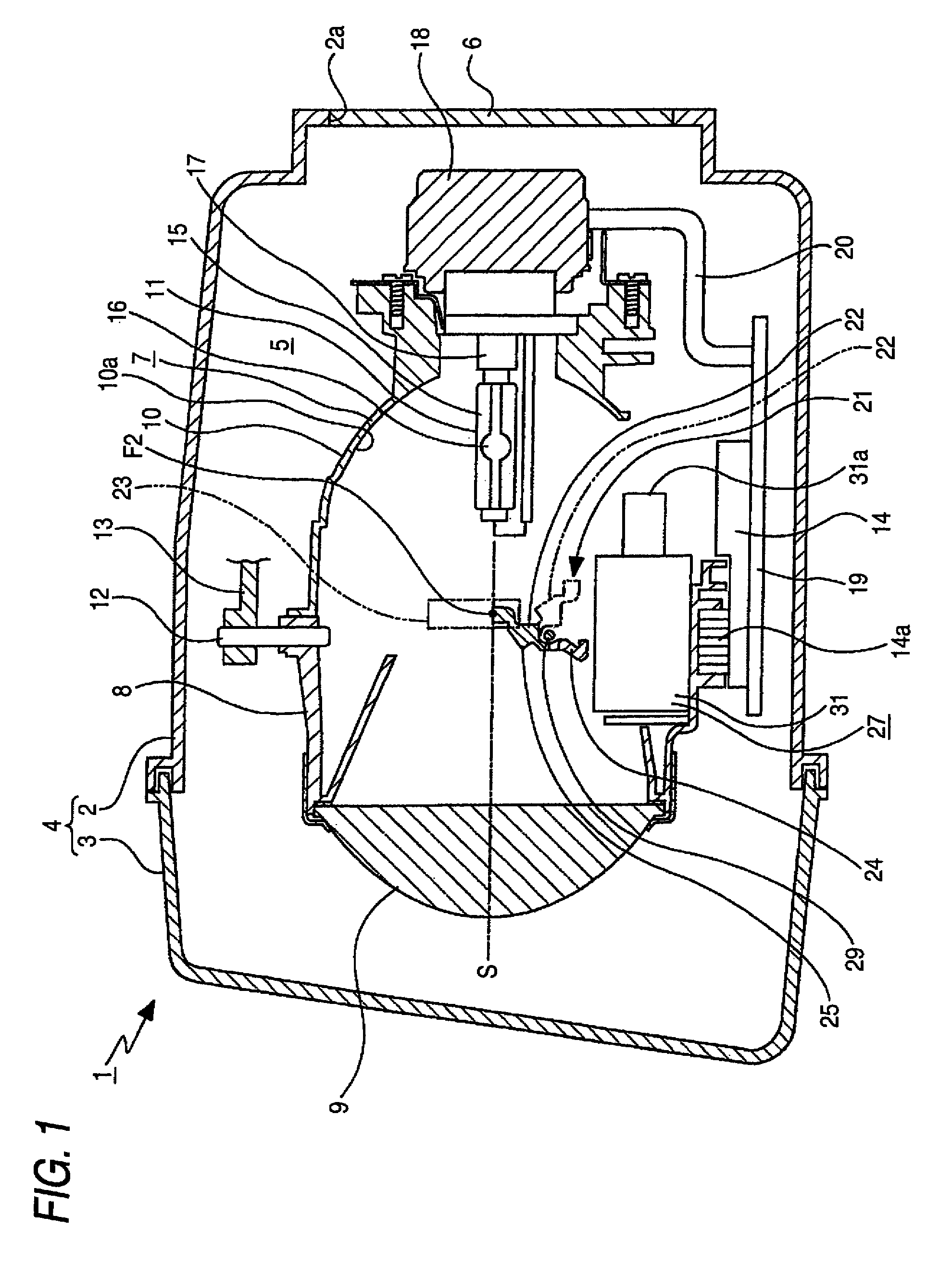
[0030]As shown in FIG. 1, the vehicle headlamp 1 includes a lamp housing 2 having a concave portion opened in a forward direction and a cover 3 for closing an opened face of the lamp housing 2. A lamp outer casing 4 is formed by the lamp housing 2 and the cover 3. An inner space of the lamp outer casing 4 is formed as a lamp chamber 5.

[0031]An attachment hole 2a penetrating in a front and rear direction of a vehicle is formed at a rear end portion of the lamp housing 2. A back cover 6 is attached to the attachment hole 2a.

[0032]A lamp unit 7 is disposed in the lamp chamber 5. The lamp unit 7 includes a lens holder 8, a projection lens 9 attached to a front end portion of the lens holder 8, a reflector 10 attached to a rear face of the lens holder 8...


PUM


Abstract

A vehicle headlamp is provided with a projection lens, a light source, a reflector, a first shade, and a second shade. The first shade includes an upper end crossing in a vicinity of a rear side focal point of the projection lens. The first shade shields a part of the light emitted from the light source and reflected by the reflector to form a first light distribution pattern. The second shade includes a light shielding portion for shielding a part of the light emitted from the light source and reflected by the reflector to form a second light distribution pattern. The second shade is movable between a first position and a second position. In the first position, the second shade is positioned above the first shade and is separated from the first shade so that the first light distribution pattern is formed. In the second position, the second shade covers the upper end of the first shade so that the second light distribution pattern is formed.

Description

BACKGROUND OF THE INVENTION[0001]1. Field of the Invention[0002]The present invention relates to a vehicle headlamp and, more in detail, relates to a technical field for smoothing an operation of shades in the vehicle headlamp having two shades for switching a light distribution pattern.[0003]2. Background Art[0004]As a vehicle headlamp, for example, there is a type in which a lamp unit having a light source is disposed within a lamp outer casing configured by a cover and a lamp housing.[0005]Some of such lamp units are configured to include a projection lens for projecting light emitted from the light source in the forward direction, a reflector for reflecting the light emitted from the light source to a side of the projection lens, and a light distribution pattern switching mechanism disposed between the projection lens and the light source. The light distribution pattern switching mechanism may have a function of switching between two light distribution patterns, that is, a light...

Claims


Application Information

Patent Timeline
Patent Type & Authority Patents(United States)
IPC IPC(8): B60Q1/00F21Y101/00
CPCF21S48/1773F21S41/686
Inventor YAMAMOTO, TERUAKI
Owner KOITO MFG CO LTD
Why Eureka
Try Eureka