Vehicle lamp

Inactive Publication Date: 2008-07-17
KOITO MFG CO LTD
View PDF2 Cites 2 Cited by
  • Summary
  • Abstract
  • Description
  • Claims
  • Application Information

AI Technical Summary

Benefits of technology

[0022]Accordingly, if the fan-like reflection region is constituted with a curved surface that deflects, diffuses, or reflects the light from the segment light source in a direction orthogonal to the first straight line L1, with the paraboloid of revolution formed as a reference plane, the deflected, diffused, or reflected light from the fan-like reflection region can be deflected or diffused so as not to stick out upward from the oblique cut-off line, and thereby the oblique cut-off line will be able to be formed clearly.
[0023]Moreover, because a light source im

Problems solved by technology

However, the vehicle headlamp described in the above “Patent Document 1” has problems in that it is not easy to clearly form an oblique cut-off line that rises obliquely with respect to the horizontal direction because the reflecting surface of the reflector is constituted with a curved surface that is formed with a paraboloid of revolution that uses the middle position of the segment light source in the right and left directi

Method used


Image

  • Vehicle lamp
  • Vehicle lamp
  • Vehicle lamp

Examples


Embodiment Construction

[0041]Hereinafter embodiments of the invention will be described with reference to the accompanying drawings.

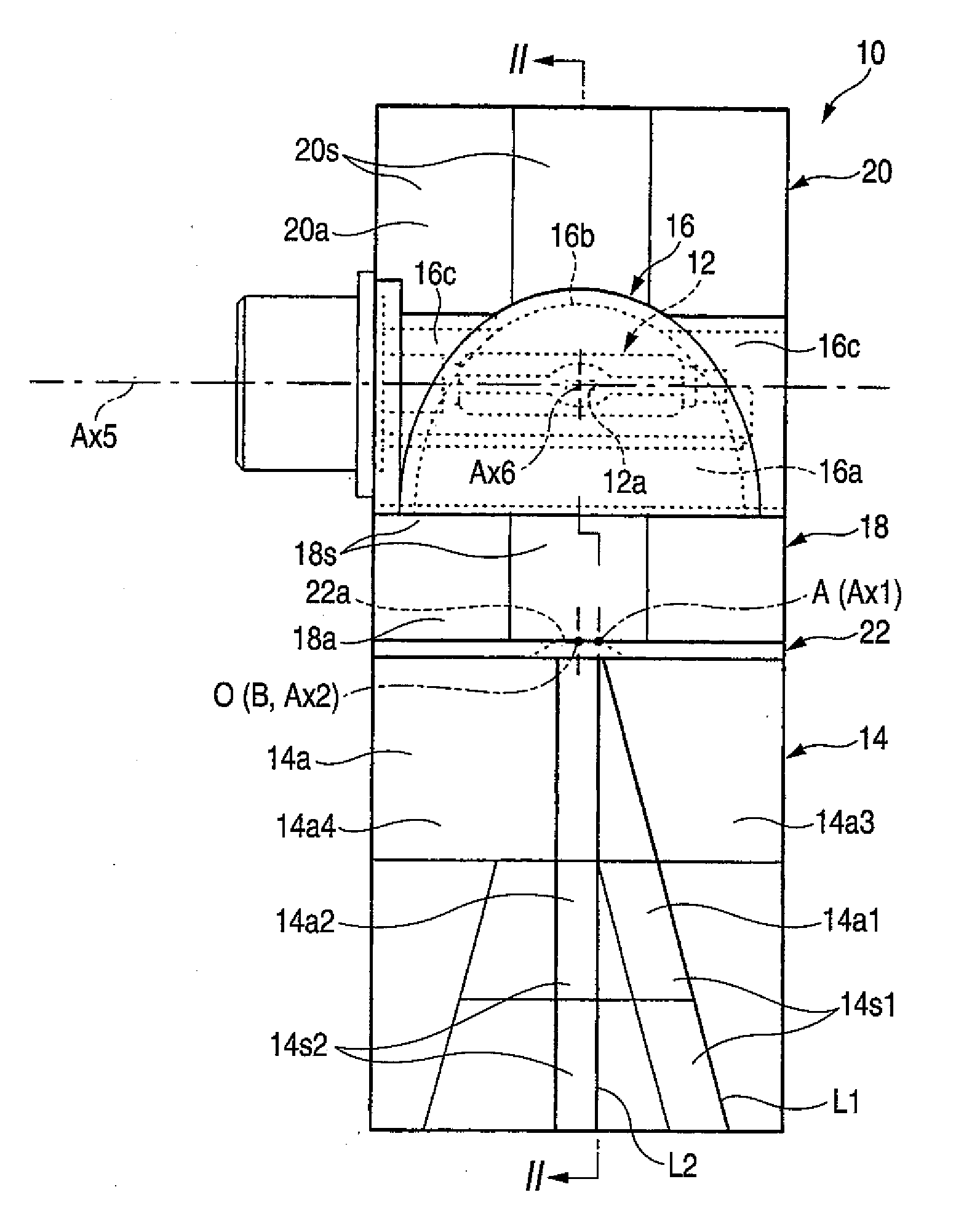
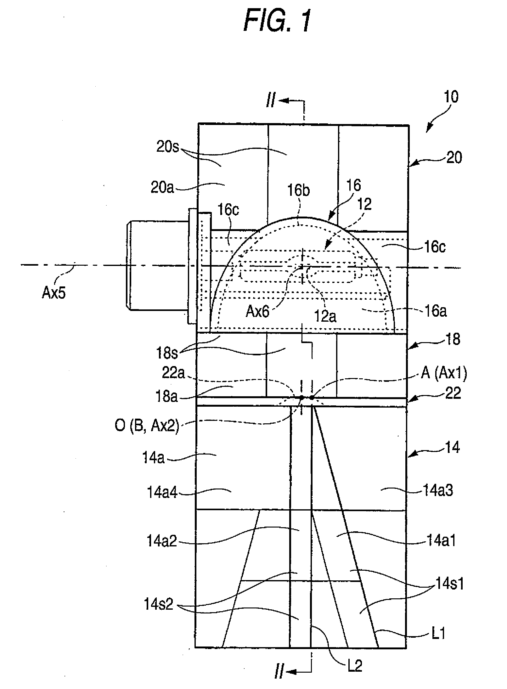
[0042]FIG. 1 is a front view showing a vehicle headlamp according to one embodiment of the invention, and FIG. 2 is a detailed sectional view taken along the line II-II. Further, FIG. 3 is a detailed sectional view taken along the line III-III of FIG. 2.

[0043]As shown in these drawings, the vehicle headlamp 10 according to the present embodiment is constituted as a lamp unit that performs light irradiation for forming a light distribution pattern for low beams. The vehicle headlamp is assembled into a lamp body that is not shown.

[0044]The vehicle headlamp 10 includes a light source bulb 12, a first reflector 14, a second reflector 16, a third reflector 18, a fourth reflector 20, and a light-shielding member 22, and has a vertically long rectangular outer shape in the plan view of the lamp.

[0045]The bulb 12 is a discharge bulb, such as, a metal halide bulb, that uses a dischar...


PUM


Abstract

A vehicle headlamp includes a reflector configured to forward reflect light from a segment light source extending in a vehicle width direction such that a light distribution pattern is formed that has a cut-off line at an upper end thereof. The segment light source is arranged such that a first predetermined point located at a front end edge of the segment light source at end edges thereof in right and left directions in a plan view of the vehicle headlamp is located on a first reference axis extending in the longitudinal direction of the vehicle. A reflecting surface of the reflector is split into a plurality of reflection regions. At least one of the plurality of reflection regions, in the plan view of the vehicle headlamp, are constituted as a fan-like reflection region surrounded by a first straight line extending obliquely downward from the first reference axis on the side of the first reference axis opposite the segment light source in the right and left directions, and a second straight line extending immediately downward from the first reference axis. The fan-like reflection region is constituted with a curved surface that deflects, diffuses, or reflects the light from the segment light source in a direction orthogonal to the first straight line, with a paraboloid of revolution that uses the first predetermined point as a focal point and uses the first reference axis as a center axis formed as a reference plane so as to form the cut-off line.

Description

[0001]This application claims foreign priority from Japanese Patent Application No. 2007-005394 filed on Jan. 15, 2007, the entire contents of which are hereby incorporated by reference.BACKGROUND OF THE INVENTION[0002]1. Field of the Invention[0003]The present invention relates to a vehicle headlamp comprising a reflector configured to forward reflect the light from a segment light source extending in a vehicle width direction such that a light distribution pattern is formed that has a cut-off line at an upper end thereof.Background Art[0004]2. Related Art[0005]Conventionally, as a vehicle headlamp, headlamps having reflectors that forward reflect the light from a segment light source extending in a vehicle width direction such that a light distribution pattern is formed that has a cut-off line at an upper end thereof are known.[0006]In typical cases, a vehicle headlamp is configured to split the reflecting surface of a reflector into a plurality of reflection regions. Each of the ...

Claims


Application Information

Patent Timeline
IPC IPC(8): B60Q1/00F21V7/00H01J9/00F21Y101/00
CPCF21S48/1388F21S41/17F21S41/321F21S41/334F21S41/43F21S41/365
Inventor TANAKA, HIDETADA
Owner KOITO MFG CO LTD
Why Eureka
Try Eureka