Optical component assembly for use with an optical device

Active Publication Date: 2014-10-02
CHIRAL PHOTONICS
View PDF40 Cites 34 Cited by
  • Summary
  • Abstract
  • Description
  • Claims
  • Application Information

AI Technical Summary

Problems solved by technology

However, there are significant challenges in interfacing optical high NA waveguide devices, including chiral optical fiber devices, with conventional low index contrast optical fibers.
Failure to properly address these obstacles results in increased insertion losses and a decreased coupling coefficient at each interface.
There are a number of significant disadvantages to this approach.
For example, a fiber cladding-capillary tube interface becomes a light guiding interface of a lower quality than interfaces inside standard optical fibers and, therefore, can be expected to introduce optical loss.
Furthermore, the capillary tube must be fabricated using a costly fluorine-doped material, greatly increasing the expense of the coupler.
Neverth

Method used


Image

  • Optical component assembly for use with an optical device
  • Optical component assembly for use with an optical device
  • Optical component assembly for use with an optical device

Examples


Embodiment Construction

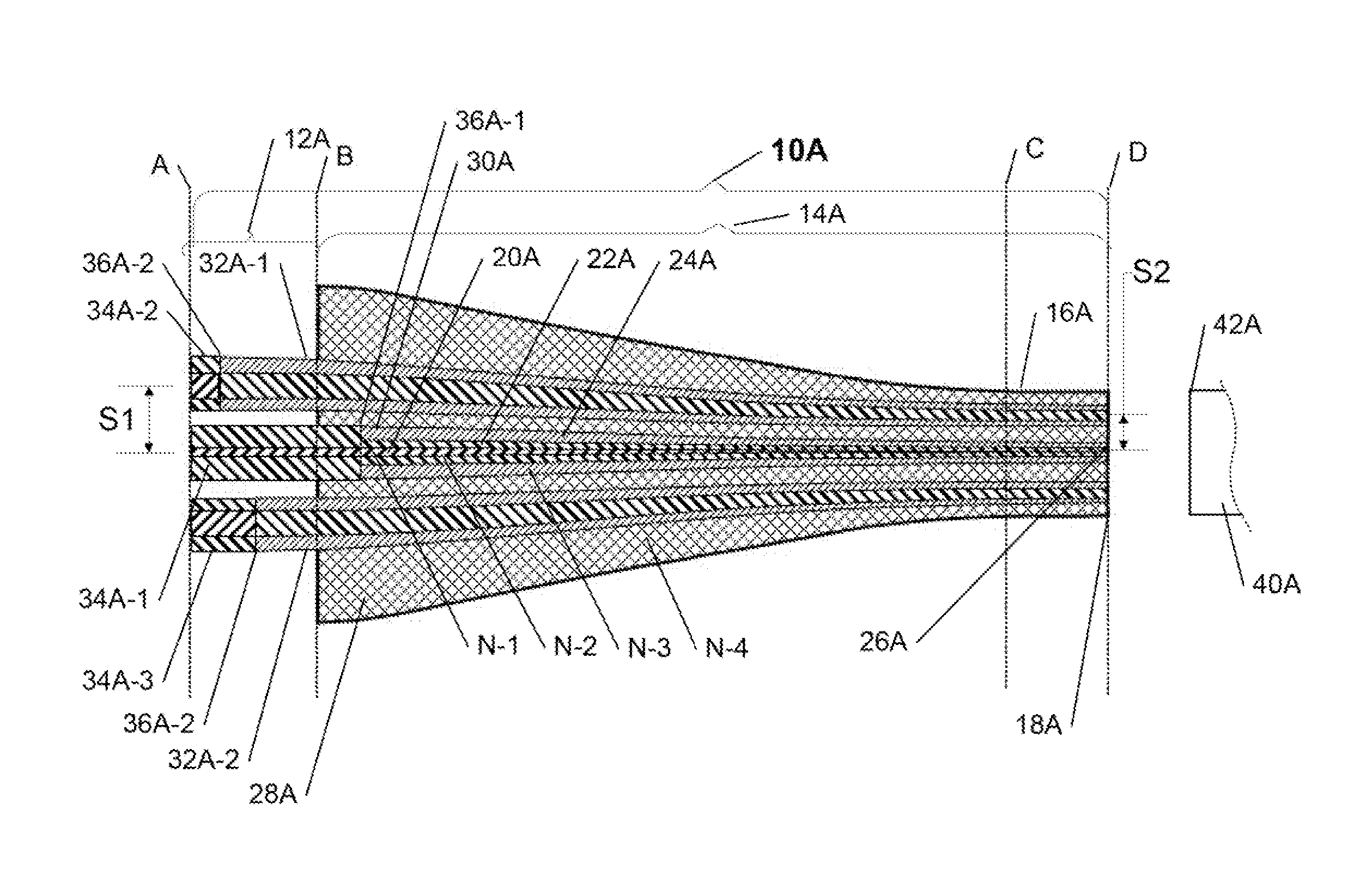
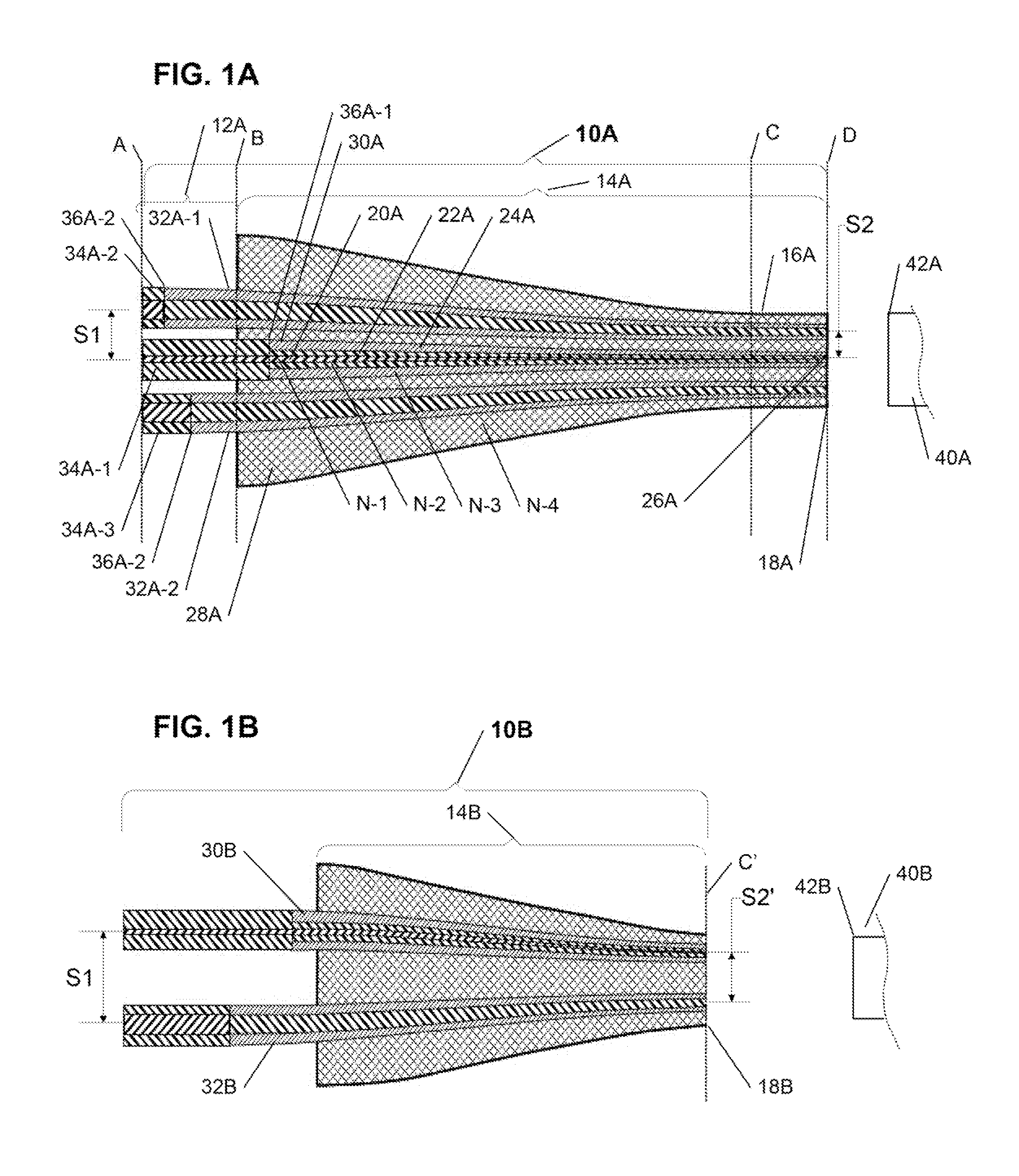
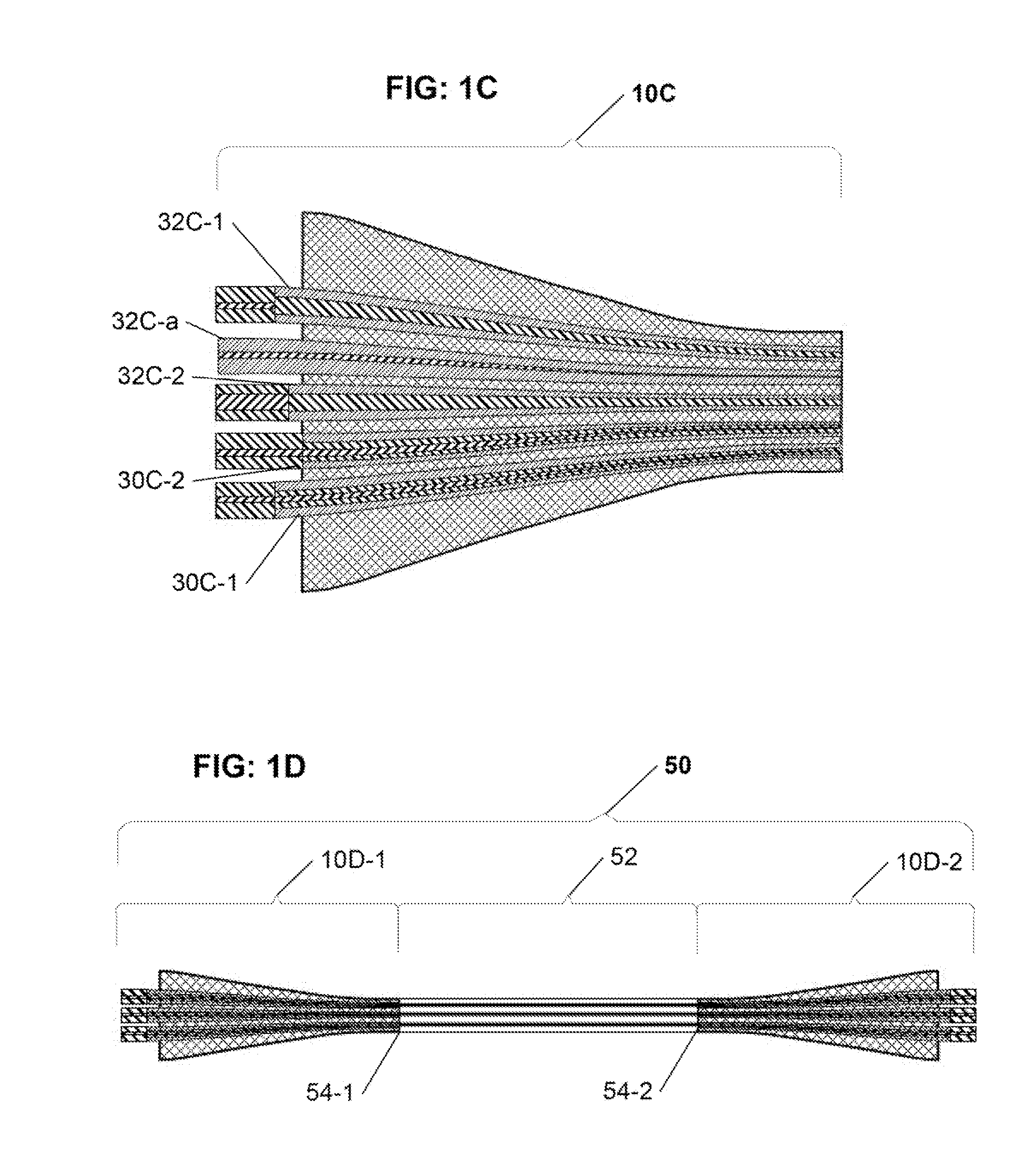
[0035]The present invention is directed to an optical fiber coupler array capable of providing a low-loss, high-coupling coefficient interface with high accuracy and easy alignment between a plurality of optical fibers (or other optical devices) with a first channel-to-channel spacing, and an optical device having a plurality of waveguide interfaces with a second, smaller channel-to-channel spacing. Advantageously, in various embodiments of the present invention, each of a larger size end and a smaller size end of the optical fiber coupler array is configurable to have a correspondingly different (i.e., larger vs. smaller) channel-to-channel spacing, where the respective channel-to-channel spacing at each of the novel optical coupler array's larger and smaller ends may be readily matched to a corresponding respective first channel-to-channel spacing of the plural optical fibers at the larger optical coupler array end, and to a second channel-to-channel spacing of the optical device ...


PUM


Abstract

The inventive optical component assembly advantageously enables a multi-waveguide optical component (such as the inventive optical fiber coupler array, a multi-core optical fiber, etc.), to be coupled to at least one waveguide of an optical device at a predefined coupling angle. The optical component assembly of the present invention comprises a multi-waveguide optical component with an output end, a prism having an input surface, an output surface, and an internal reflective surface with a predefined reflection angle, and a GRIN lens, positioned between the component output end and the prism input surface, along a longitudinal axis of the multi-waveguide optical component. In accordance with the present invention, the length of the GRIN lens, and its refractive index gradient profile are optimized to form an optical image of the output end of the multi-waveguide optical component, at the output surface of the prism, thus enabling the output surface of the prism to be coupled to at least one waveguide of an optical device, with the predefined reflection angle corresponding to the angle at which the multi-waveguide optical component may be coupled to the optical device.

Description

CROSS REFERENCE TO RELATED APPLICATIONS[0001]The present application is a continuation-in-part of, and claims priority from, the commonly assigned co-pending U.S. patent application Ser. No. 13 / 830,865 (Atty Docket No. 1014-39CIP), which in turn is a continuation of, and claims priority from, the commonly assigned co-pending U.S. patent application Ser. No. 13 / 692,989 (Atty Docket No. 1014-39-CLINK), which in turn is a continuation of, and claims priority from, the commonly assigned U.S. patent application Ser. No. 12 / 502,613—now U.S. Pat. No. 8,326,099 (Atty Docket No. 1014-39), which in turn claims priority from commonly assigned U.S. Provisional Patent Application Ser. No. 61 / 080,684 (Atty Docket No. 1014-39PROV), all of which are incorporated herein by reference in their entirety; and which further variously claims priority at least from the following commonly assigned patent applications: Application Ser. No. 61 / 606,681 (Atty Docket No. 1014-39CIP-PROV), Application Ser. No. 61...

Claims


Application Information

Patent Timeline
IPC IPC(8): G02B6/28
CPCG02B6/2848G02B6/26G02B6/30G02B6/2804G02B6/305
Inventor KOPP, VICTOR IL'ICHSINGER, JONATHANNEUGROSCHL, DANIELPARK, JONGCHULWLODAWSKI, MITCHELL S.
Owner CHIRAL PHOTONICS
Why Eureka
Try Eureka