Insert for shear-type flexible shaft couplings

a flexible shaft and inserting technology, applied in the direction of inserting couplings, couplings, mechanical instruments, etc., can solve the problems of overshadowing of service costs of inserts and retaining rings, and achieve the effect of less expensiv

Inactive Publication Date: 2014-10-02
LOUWERSHEIMER FREDERIK JAN
View PDF8 Cites 3 Cited by
  • Summary
  • Abstract
  • Description
  • Claims
  • Application Information

AI Technical Summary

Benefits of technology

[0004]Embodiments of the present invention addresses this need by providing a new insert for shear-type shaft couplings that has a unitary construction, that parallels or exceeds the performance of existing conventional inserts, and is less expensive than conventional inserts.

Problems solved by technology

And in such circumstances the cost of the insert and retaining ring are generally quickly over shadowed by the service costs to move the shafts.
But during original equipment manufacture the need to use an expensive multi-piece insert assembly including the belt-like insert and the separate retaining ring is not required because the shafts are easily moveable.

Method used


Image

  • Insert for shear-type flexible shaft couplings
  • Insert for shear-type flexible shaft couplings
  • Insert for shear-type flexible shaft couplings

Examples


Embodiment Construction

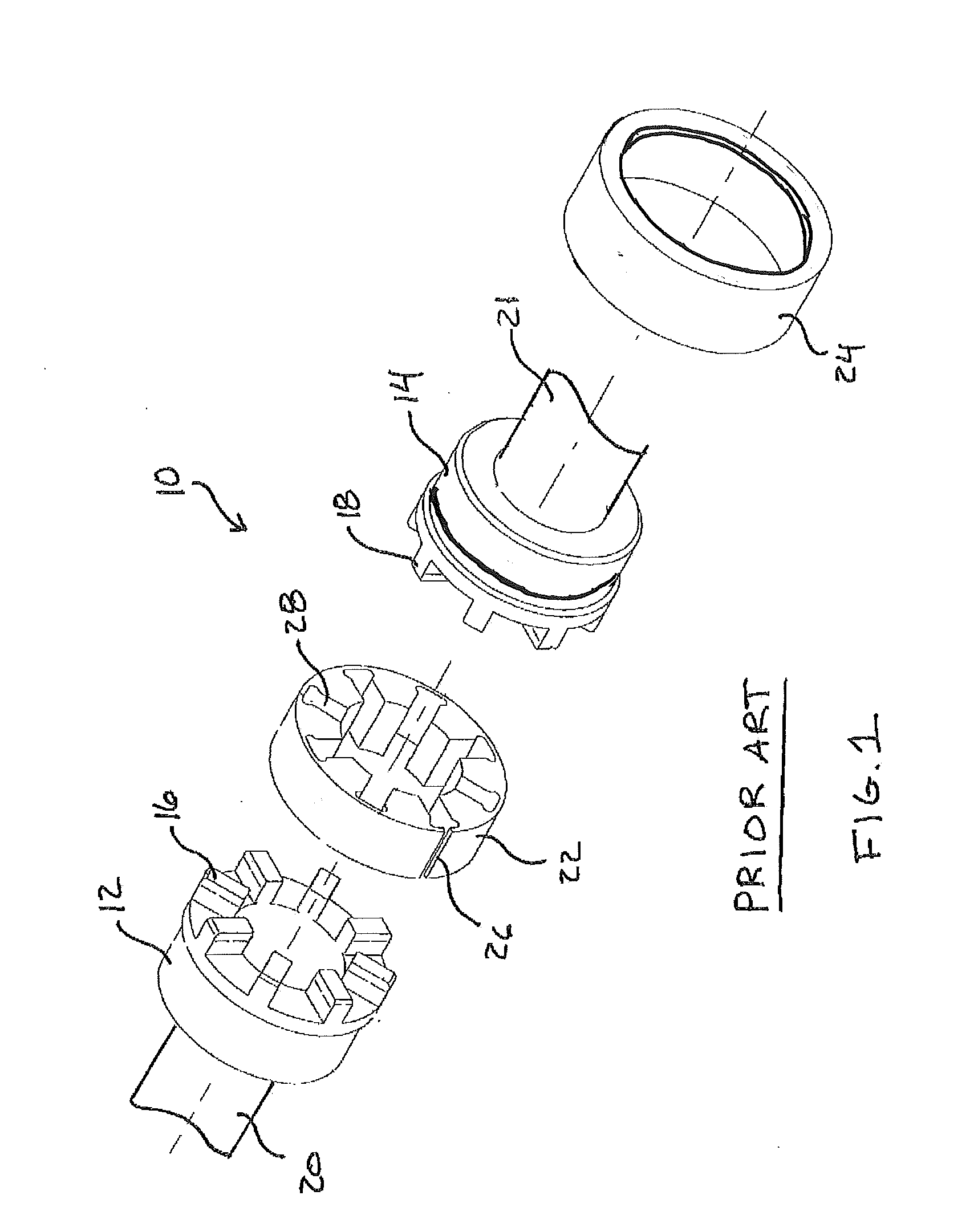
[0016]With reference to FIG. 1 there is illustrated an exploded perspective view of a typical toothed shear-type coupling 10. The coupling conventionally has two cylindrical shaft hubs 12 and 14, an insert 22, and a retaining ring 24. Each hub 12 and 14 has a plurality of radial hub teeth 16 and 18, respectively. Hub 12 is mounted to a driving shaft 20 and hub 14 is mounted to a driven shaft 21. Insert 22 includes a radial slit 26 and plurality of axially extending slots 28. The slit 26 permits the insert to be unwrapped or opened and then wrapped around the hub teeth 16 and 18, positioning the teeth within a corresponding slot 28, connecting hubs 12 and 14 together. Retaining ring 24 encircles insert 22 to prevent radial expansion or unwrapping of the insert when the coupling is under load and from rotation. Retaining ring 24 is secured in place by a spring-clip (not shown).

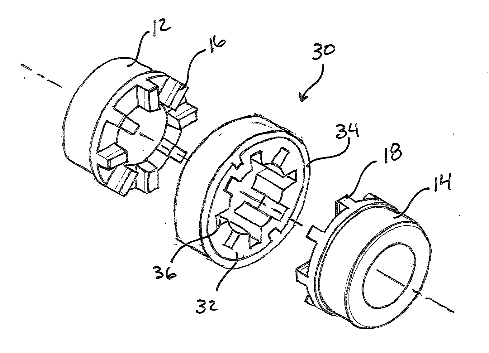
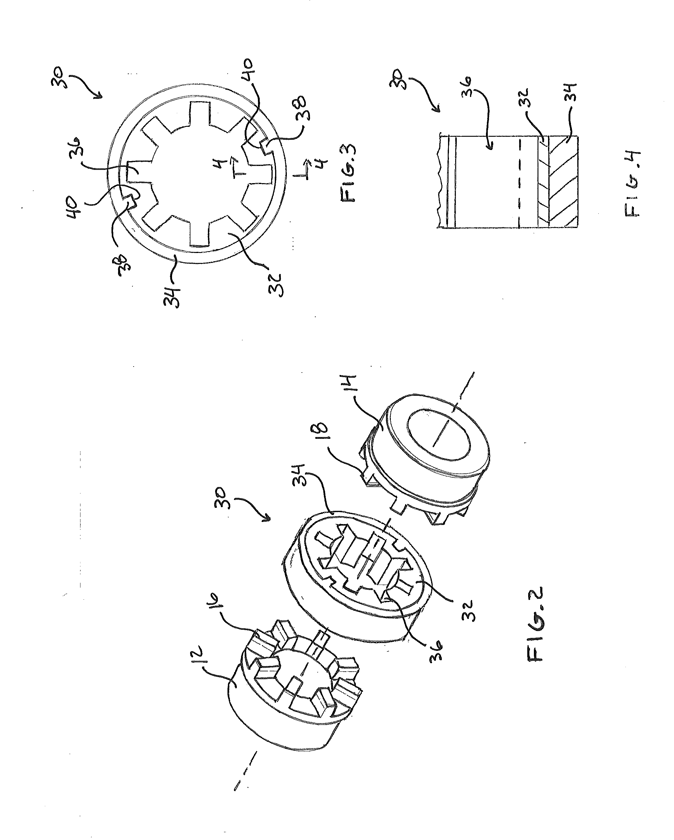
[0017]With reference to FIGS. 2 through 4, there is illustrated a new insert 30 constructed in accordance wit...


PUM


Abstract

A non-split, unitary insert for a shear-type flexible shaft coupling is provided. The insert has an inner ring and an outer ring that is non-removably joined to and encircles the inner ring. The inner ring is constructed of a material having a durometer that is less than the durometer of the material forming the outer ring. In embodiments both of these materials are polyurethane. This arrangement permits slots of the inner ring to shear while retaining the integrity of insert by preventing destruction of the outer ring during shear of the slots. The outer ring may include one or more radial tabs that are received by corresponding one or more radial notches in the inner ring to prevent separation of the rings under load.

Description

FIELD OF THE INVENTION[0001]The present invention relates generally to shear-type shaft couplings having opposing hubs that are connected by a destructible insert, and more particularly, relating to an insert member of a unitary construction having a destructible inner ring and a non-destructible outer ring that is non-removably conjoined with the inner ring.BACKGROUND OF THE INVENTION[0002]Flexible shaft couplings are used to transmit rotational power between a driving shaft connected to a prime mover and a driven shaft connected to a load. The flexible coupling allows for both radial and axial misalignment of the two shafts. One conventional flexible coupling, to which the present invention is directed, includes a pair of hubs, an elastomeric belt-like insert that is disposed between and connects the hubs, and a retaining ring that encircles the insert. The hubs have teeth extending axially from generally confronting hub faces that are received in slots of the centrally disposed i...

Claims


Application Information

Patent Timeline
Patent Type & Authority Applications(United States)
IPC IPC(8): F16D3/74
CPCF16D3/74F16D3/54F16D3/68
Inventor LOUWERSHEIMER, FREDERIK JAN
Owner LOUWERSHEIMER FREDERIK JAN
Why Eureka
Try Eureka