Separable actuator

a technology of actuators and actuators, applied in the field of actuators, can solve the problems of user inflexible selection of user requirements, user inability to easily set the decelerator ratio, and increased size of the decelerator, and achieve the effect of high degree of freedom

Active Publication Date: 2014-10-09
ROBOTIS
View PDF2 Cites 42 Cited by
  • Summary
  • Abstract
  • Description
  • Claims
  • Application Information

AI Technical Summary

Benefits of technology

[0012]In another embodiment, provided is a separable actuator module capable of providing various applications according to the needs of a user through a high degree of freedom, expandability, and compatibility.
[0027]According to the embodiments above, the separable actuator module is modularized into the primary deceleration module and the secondary deceleration module to enable flexible selection by a user. In addition, various applications are possible according to the needs of the user via a high degree of freedom, expandability, and compatibility.

Problems solved by technology

However, considering the various decelerators including the above-mentioned related technologies, since the deceleration gear is installed in one housing, the size of the decelerator is increased and a user cannot easily set the deceleration ratio.
In addition, the user cannot flexibly select his / her requirements (e.g., a center distance, a gear-type, a gear ratio, and the like).

Method used


Image

  • Separable actuator
  • Separable actuator
  • Separable actuator

Examples


Embodiment Construction

[0038]Hereinafter, an exemplary embodiment of the present invention will be described with reference to FIGS. 1 to 3. The embodiment of the present invention may be modified in various types, and the scope of the present invention should not be limited to the embodiments to be described below. The embodiments are provided to describe the present invention to those skilled in the art in detail. Accordingly, shapes of elements shown in the drawings may be exaggerated to emphasize clearer description thereof

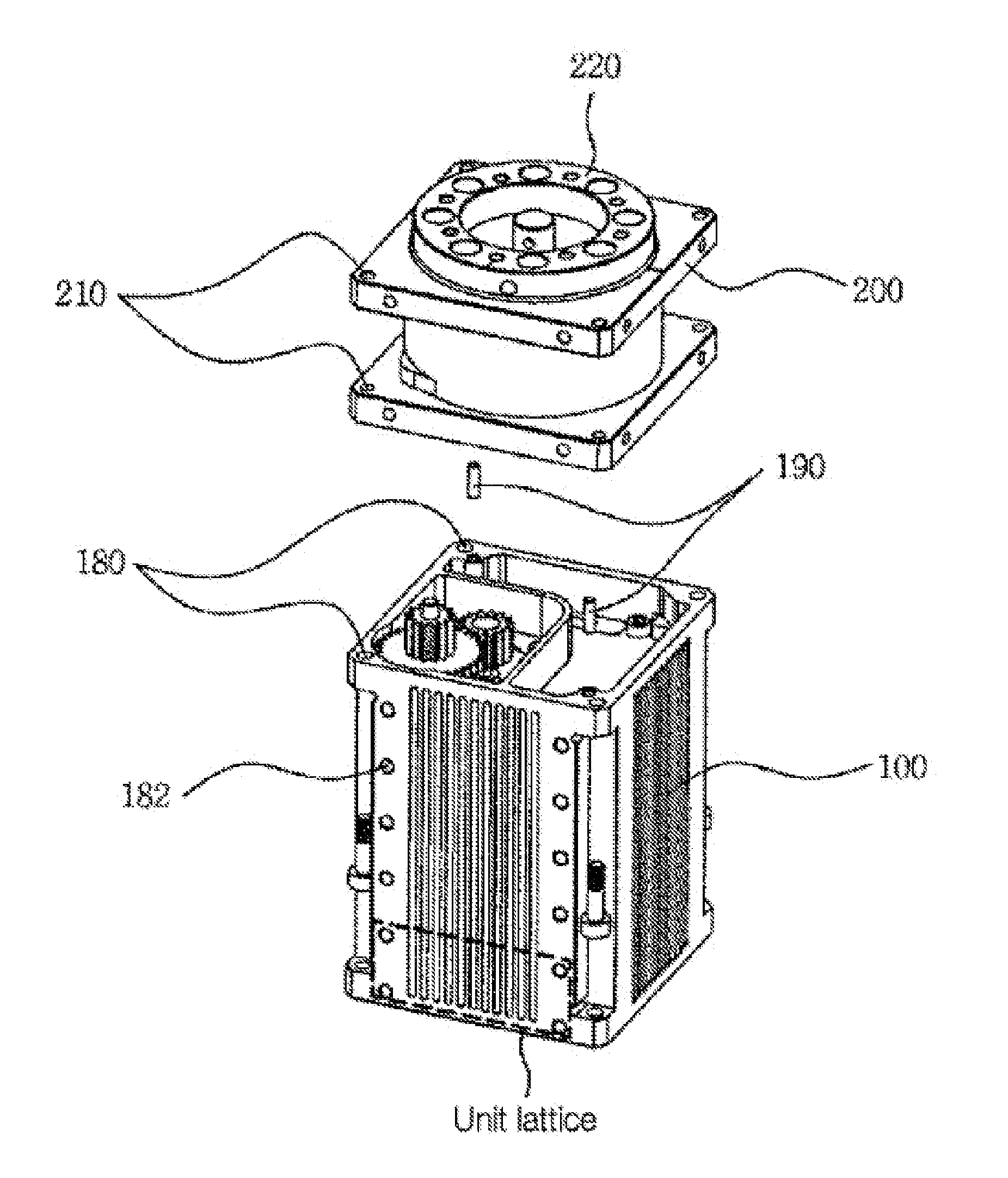
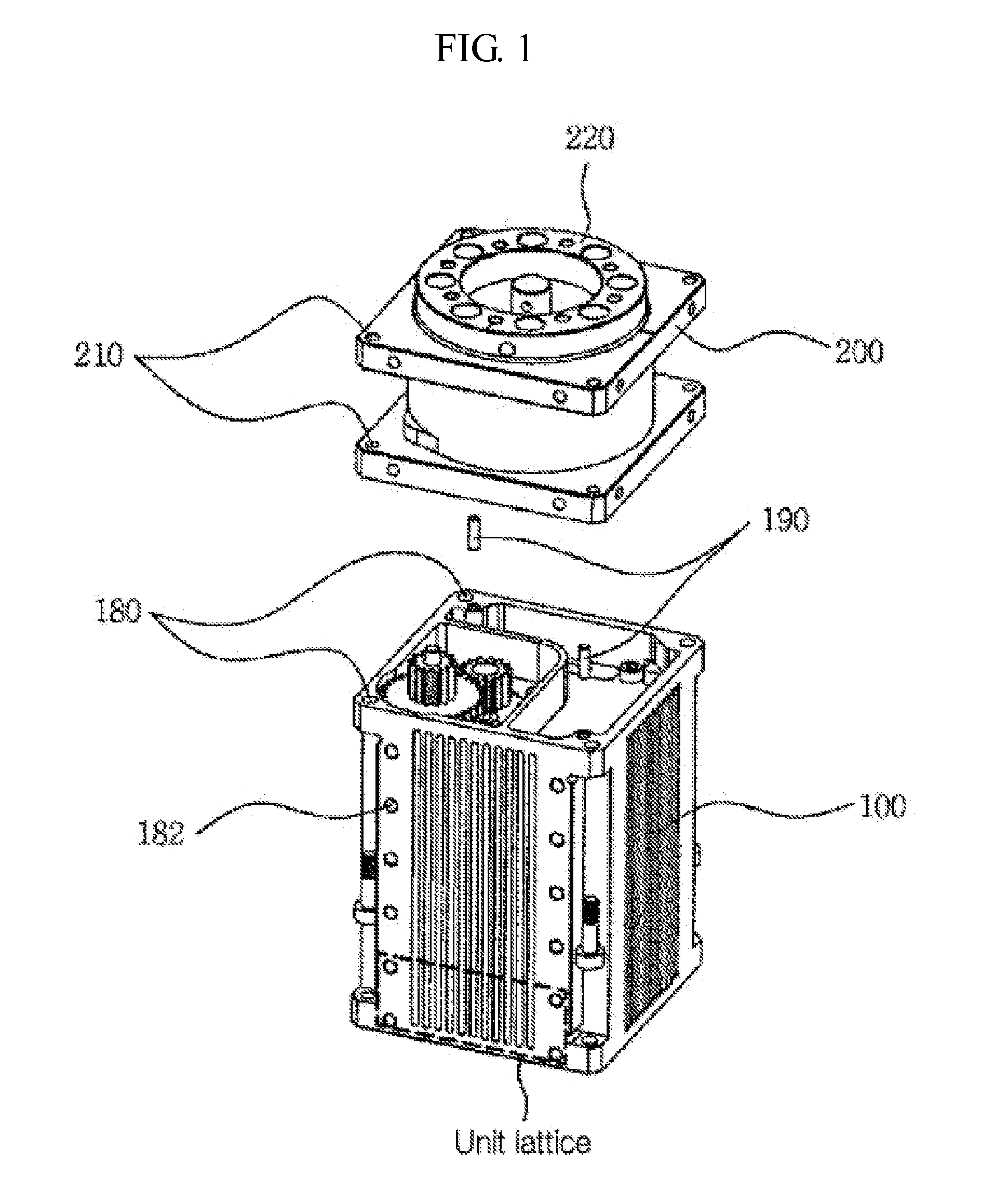
[0039]As shown in FIG. 1, a separable actuator according to the present invention includes a primary deceleration module 100 and a secondary deceleration module 200.

[0040]Here, the primary deceleration module 100 may be commonly used and the plurality of secondary deceleration modules 200 are configured to provide various deceleration ratios in order to implement the various deceleration ratios and degrees of freedom. Further, when the plurality of primary deceleration modules 100 a...


PUM


Abstract

An actuator for controlling joint movement of a robot includes a first deceleration module and a second deceleration module, which receives and outputs driving force by being in gear with the first deceleration module. The first deceleration module includes a driving motor, a first print circuit board for controlling the driving motor by feeding back the output of the second deceleration module, at least one first reduction gear which is rotated by a driving motor, and a housing on which the driving motor, the first print circuit board, and the first reduction gear are mounted. The second deceleration module includes at least one other reduction gear, which rotates by being in gear with the first reduction gear, and a case on which the second reduction gear is mounted and which is connected to the housing.

Description

CROSS REFERENCE TO RELATED APPLICATIONS AND CLAIM OF PRIORITY[0001]This patent application is a National Phase application under 35 U.S.C. §371 of International Application No. PCT / KR2012 / 008902, filed Oct. 26, 2012, which claims priority to Korean Patent Application No. 10-2011-0110070 filed Oct. 26, 2011, entire contents of which are incorporated herein by reference.BACKGROUND[0002]1. Field of the Invention[0003]The present invention relates to an actuator for controlling motion.[0004]2. Description of the Related Art[0005]Robots, from industrial robots to humanoid robots, are widely used and can perform flexible articulated motions through actuators having a deceleration function.[0006]In particular, within the robotics industry, which has rapidly developed in recent times, robotics mechanisms that have only been used in specific industrial fields are also being applied to broader industrial fields leading to a convergence of technologies. For example, home cleaning robots, progr...

Claims


Application Information

Patent Timeline
Patent Type & Authority Applications(United States)
IPC IPC(8): F16H1/20F16H35/00
CPCB25J9/1025F16H35/00F16H1/20B25J9/126F16H1/32F16H37/041H02K7/116H02K11/30Y10T74/19637B25J19/00F16H1/00
Inventor KIM, BYOUNG-SOOLEE, JUNG-HO
Owner ROBOTIS
Why Eureka
Try Eureka