
Elastic averaging alignment system, method of making the same and cutting punch therefor

a technology of elastic averaging and alignment system, applied in the direction of cross-cut reciprocating saws, sawing apparatus, metal working apparatus, etc., can solve the problem of not providing a predetermined alignment of components

Inactive Publication Date: 2014-10-09
GM GLOBAL TECH OPERATIONS LLC
View PDF8 Cites 31 Cited by
  • Summary
  • Abstract
  • Description
  • Claims
  • Application Information

AI Technical Summary

Benefits of technology

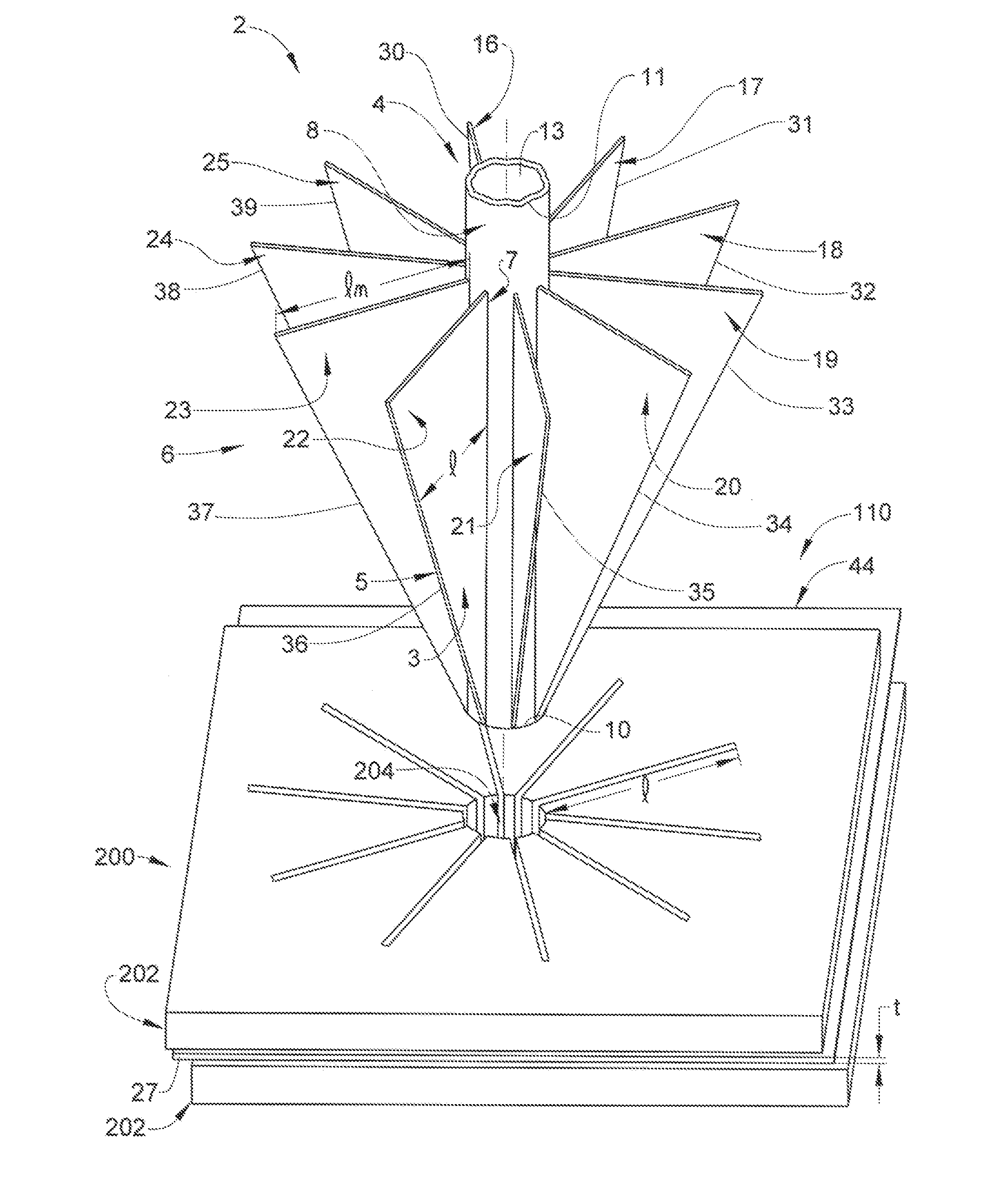
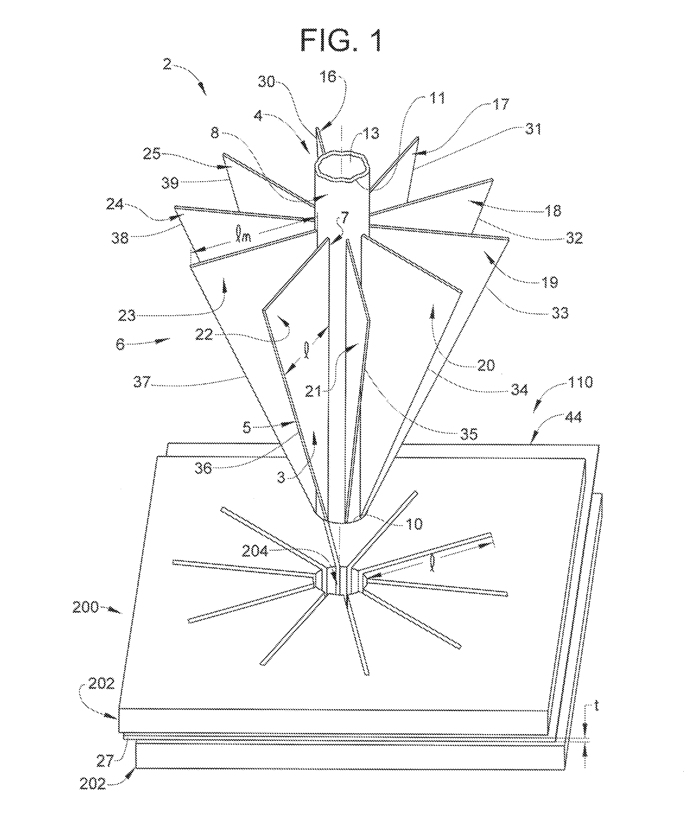
The patent text describes a cutting punch and a method for making a component alignment system. These innovations have technical benefits that improve the accuracy and efficiency of the manufacturing process. The cutting punch has a central punching member and at least one cutting element extending radially outward from it, which helps to align and cut components accurately. The method involves forming a plurality of elastically deformable apertures through a first component, which have a unique shape and can align and deform to fit the surface of another component. This helps to create a more precise alignment. Overall, these innovations improve the speed, accuracy, and reliability of the manufacturing process.

Problems solved by technology

While existing systems enable relative alignment of the components by allowing sufficient relative movement, the engagement of the alignment features (i.e., insertion of the protruding features in the holes) does not provide a predetermined alignment of the components, but only allows relative movement by an operator, tool, gauge or the like to obtain their desired alignment.

Method used


Image

  • Elastic averaging alignment system, method of making the same and cutting punch therefor
  • Elastic averaging alignment system, method of making the same and cutting punch therefor
  • Elastic averaging alignment system, method of making the same and cutting punch therefor

Examples


Embodiment Construction

[0020]The following description is merely exemplary in nature and is not intended to limit the present disclosure, its application or uses. It should be understood that throughout the drawings, corresponding reference numerals indicate like or corresponding parts and features.

[0021]As used herein, the term “elastically deformable” refers to components, or portions of components, including component features, comprising materials having a generally elastic deformation characteristic, wherein the material is configured to undergo a resiliently reversible change in its shape, size, or both, in response to application of a force. The force causing the resiliently reversible or elastic deformation of the material may include a tensile, compressive, shear, bending or torsional force, or various combinations of these forces. The elastically deformable materials may exhibit linear elastic deformation, for example that described according to Hooke's law, or non-linear elastic deformation.

[00...


PUM

PropertyMeasurementUnit
Thicknessaaaaaaaaaa
Shapeaaaaaaaaaa

Abstract

An elastic averaging alignment system includes a first component comprising a surface, a thickness and a plurality of elastically deformable apertures spaced apart on the surface and extending through the thickness, each of the elastically deformable apertures comprising an aperture peripheral shape and having at least one slit extending radially-outwardly therefrom defining at least one elastically deformable wedge member. A method of making a component alignment system includes providing a first component having a surface and a thickness. The method also includes forming a plurality of alignment features through the thickness of the first component, the alignment features comprising a plurality of elastically deformable apertures spaced-apart on the surface and extending through the thickness, each of the elastically deformable apertures comprising an aperture peripheral shape and having at least one slit extending radially-outwardly therefrom defining at least one elastically deformable wedge member.

Description

FIELD OF THE INVENTION[0001]The subject invention relates to an elastic averaging alignment system and method for use with compliant materials and to the art of cutting punches and, more particularly, to cutting punches for use in forming elastic averaging features in compliant materials.BACKGROUND[0002]There exist numerous systems for aligning two or more components. In some cases, one component will include alignment pins, threaded rods, or other similar projecting structures. The projecting structures are configured to be received by oversized openings in a second component to facilitate a desired alignment. Generally, there exists a need to maintain tolerances between the projecting structure and corresponding openings sufficient to achieve the desired alignment of the components, including both two-way and four-way alignment. Using these alignment systems, misalignments may be magnified and tolerances may stack-up when the first member includes two or more spaced-apart projecti...

Claims


Application Information

Patent Timeline
IPC IPC(8): B26F1/14
CPCB26F1/14Y10T83/04Y10T83/8878Y10T83/9428
Inventor MORRIS, STEVEN E.LAWALL, JENNIFER P.COLOMBO, JOELKONCHAN, JEFFREY L.
Owner GM GLOBAL TECH OPERATIONS LLC
Learn More