Suction disk structure

a technology of suction disk and adsorption disk, which is applied in the direction of shaving accessories, machine supports, other domestic objects, etc., can solve the problems of large rotary force, inability to move the bar up and down, and the adsorption of soft rubber suction disk is not tight or easy to loosen, etc., to achieve stable adsorption effect, improve adsorption force, and improve the effect of adsorption

Active Publication Date: 2014-10-16
ANHO HOUSEWARE CO LTD JIANGMEN
View PDF3 Cites 6 Cited by
  • Summary
  • Abstract
  • Description
  • Claims
  • Application Information

AI Technical Summary

Benefits of technology

[0005]Based on the above, the technical problem to be solved according to the present application is to provide a suction disk structure which has a strong adsorption force and a long-term stable adsorption effect, and with this structure, it is not easy for the hung articles to fall off, and the operation is more convenient and easy.
[0019]Compared with the prior art, in the suction disk structure according to the present application, since an inclined step pushing type driving device is employed, the pushing switch is driven to slide back and forth in the radial direction under the action of the driving slide cover, it is easy for the pin shaft at the end of the draw bar to be pushed up and down by the inclined steps at the center of the suction disk, the pin shaft is moved up and down along the inclined steps and can be stopped on the upper and lower end supporting surfaces of the inclined steps, respectively. Thereby the draw bar is driven to rise and fall to drive the soft rubber suction disk to be in the adsorption state and the release state. It is easy to push the pushing switch until it is in the self-locking state. At the same time, the base may serve as not only a back support for the soft rubber suction disk, but also as a sliding seat for the pushing switch. The base may also serve as a shell of the main body of the suction disk. The appearance of the entire suction disk may have various shapes, for example, a square shape, a circular shape, an oval shape or a polygon shape. Thereby, with such a suction disk, the installation environment becomes tidy, beautiful and generous, the adsorption force is improved, the adsorption effect is stable, the hanging article will not be easily fall off, the operation is more simple and easier, and the structure is simple and beautiful.

Problems solved by technology

Disadvantages of these structures are that: the structure is complex, large rotary force is required, the draw bar can not be moved up and down in position due to insufficient rotation, therefore the adsorption of the soft rubber suction disk is not tight or easy to get loosen, and thus the hung article is likely to fall off.

Method used


Image

  • Suction disk structure
  • Suction disk structure
  • Suction disk structure

Examples


Embodiment Construction

[0102]In order that technical solutions according to the present application can be better understood by those skilled in the art, hereinafter, the technical solutions will be described in conjunction with embodiments.

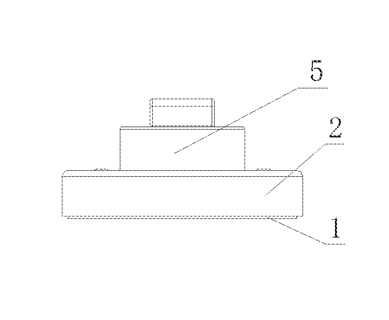
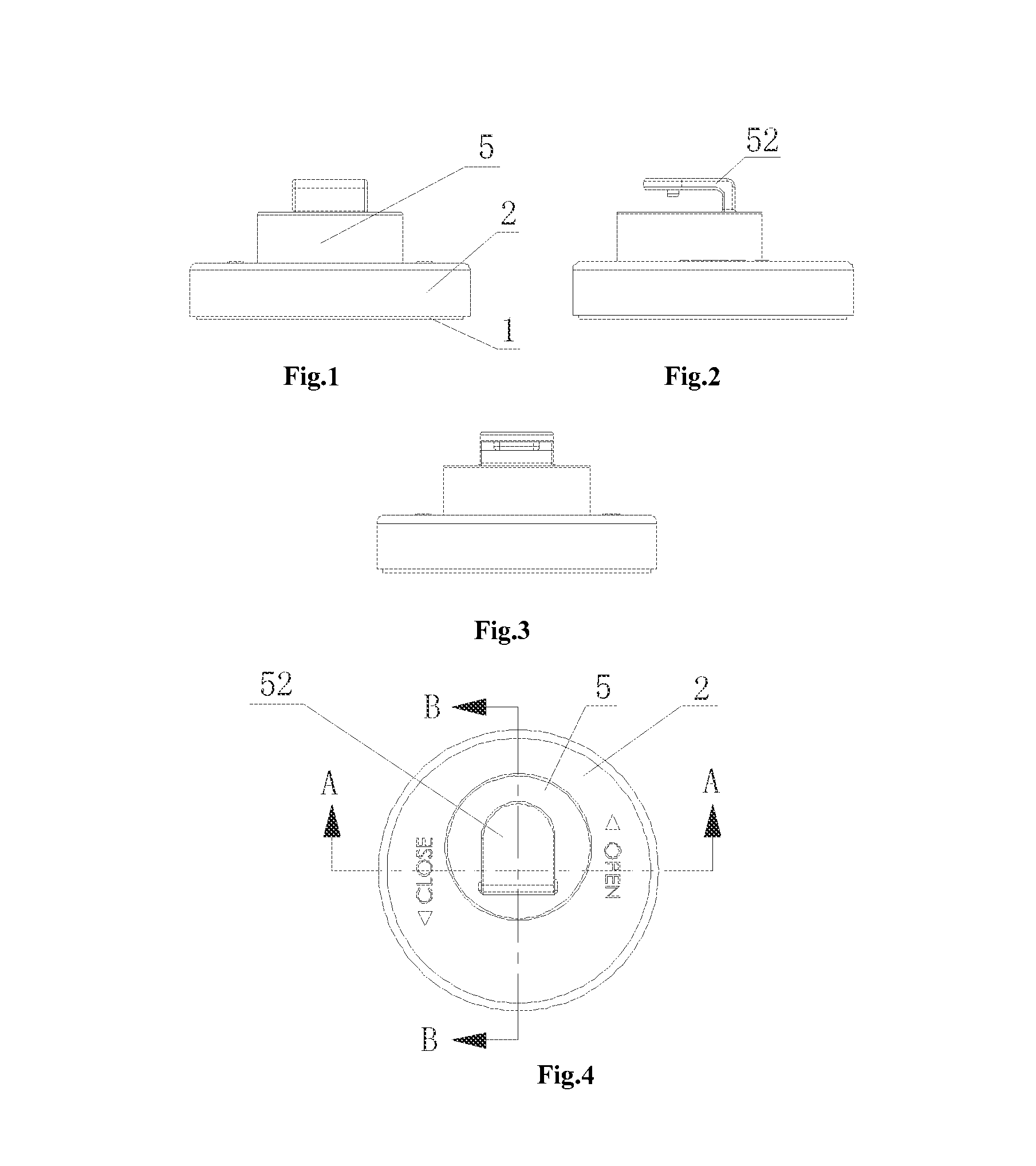
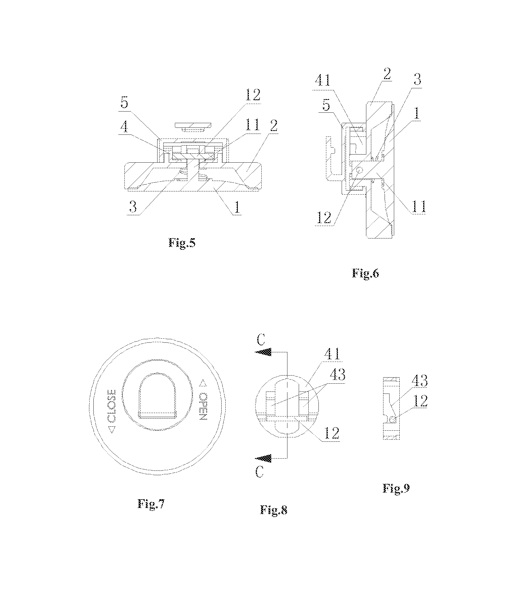
[0103]As shown in FIGS. 1 to 82, a suction disk according to an embodiment of the present application includes: a soft rubber suction disk 1 with a draw bar 11, a base 2 mounted on the back face of the soft rubber suction disk 1, and a return spring 3 located between the soft rubber suction disk 1 and the base 2. An end of the draw bar 11 is provided with a pin shaft 12 radially extended towards two sides of the draw bar. The suction disk further includes a driving device 4 for driving the draw bar 11 to rise and fall by pushing the pin shaft 12. The center of the base 2 has a central guiding hole 21 for guiding the draw bar 11 to move axially. A guiding column 23 having symmetrical guiding planes 22 at two sides of the guiding column and a pair of symmetrical position...


PUM


Abstract

A suction disk structure including: a soft rubber suction disk (1) with a draw bar (11), a base (2) provided on a back face of the soft rubber suction disk (1) and a return spring (3) located between the soft rubber suction disk (1) and the base (2). Two sides of an end of the draw bar (11) is provided with a pin shaft (12) radially extended, and the suction disk further includes a driving device (4) for driving the draw bar (11) to rise and fall. The driving device (4) comprises a pushing switch (41) mounted on the base (2) and a driving slide cover (5) connected with the pushing switch. The pin shaft (12) can be driven to move up and down along the inclined step (43) at the center of the driving device, and the pin shaft (12) is moved up and down along the inclined step (43) and can be stopped on the upper and lower end supporting surfaces of the inclined step, respectively, thereby driving the draw bar (11) to rise and fall to drive the soft rubber suction disk, to thereby achieving an adsorption state and a release state. The pushing switch (41) can be easily pushed to the end to be is in a self-locking state, and the suction disk structure has a strong adsorption force and is easy to operate.

Description

This application claims the benefit of priority to the following Chinese Patent Applications, the entire disclosures of which are incorporated herein by reference:[0001]1) Application No. 201220285179.6 entitled “SUCTION DISK STRUCTURE” and filed with the Chinese State Intellectual Property Office on Jun. 15, 2012; and[0002]2) Application No. 201310044753.8 entitled “SUCTION DISK STRUCTURE” and tiled with the Chinese State Intellectual Property Office on Feb. 4, 2013.FIELD OF THE INVENTION[0003]The present application relates to a field of a suction cup for attaching, and in particular, to a suction disk structure.BACKGROUND OF THE APPLICATION[0004]The suction disk in the prior art has a simple structure and low cost, is easy to make, and is widely used in various fields. Especially, in our daily life, it is usually used to hang articles on the wall or the glass. One structure includes a soft rubber suction disk with a draw bar, a base provided on the back face of the soft rubber su...

Claims


Application Information

Patent Timeline
Patent Type & Authority Applications(United States)
IPC IPC(8): F16B47/00
CPCA47G1/17F16B47/00A47G29/087
Inventor ZHANG, DECAI
Owner ANHO HOUSEWARE CO LTD JIANGMEN
Why Eureka
Try Eureka