
Transparent display device and transparent display panel

a technology of transparent display and display panel, which is applied in the direction of identification means, lighting and heating apparatus, instruments, etc., can solve the problems of unclear image, image in the the arrangement of pixels of the transparent display panel has more problems relative to a traditional flat panel, so as to improve the problem of conventional transparent display device, improve the effect of resolution and poor definition

Inactive Publication Date: 2014-10-16
AU OPTRONICS CORP
View PDF5 Cites 40 Cited by
  • Summary
  • Abstract
  • Description
  • Claims
  • Application Information

AI Technical Summary

Benefits of technology

The present invention aims to improve the resolution and clarity of transparent display devices. It achieves this through a mode switch that can go from a high to lower transparency display mode, allowing for clear images in high resolution. The result is a transparent display device that can provide better clarity and definition without being affected by interferences in the transparent state.

Problems solved by technology

However, since the performance of both the transparent displaying state and the image displaying state have to be considered in the transparent display device, the arrangement of pixels of the transparent display panel has more problems relative to a traditional flat panel.
These problems can result in unclear image, such as rough boundary of image.
For example, the images in the conventional transparent display device have the common problem that they have rough fringes of image shapes.
Furthermore, the displayed images of the conventional transparent display device are also interfered by the transparent displaying state, so that the conventional transparent display device cannot clearly show animations, movies, and photographs.
Therefore, the application field of conventional transparent display device is restricted.

Method used


Image

  • Transparent display device and transparent display panel
  • Transparent display device and transparent display panel
  • Transparent display device and transparent display panel

Examples


Embodiment Construction

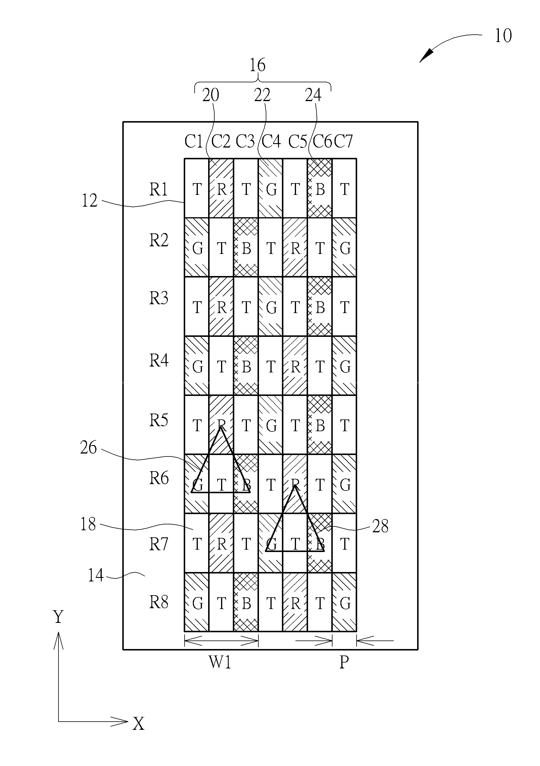
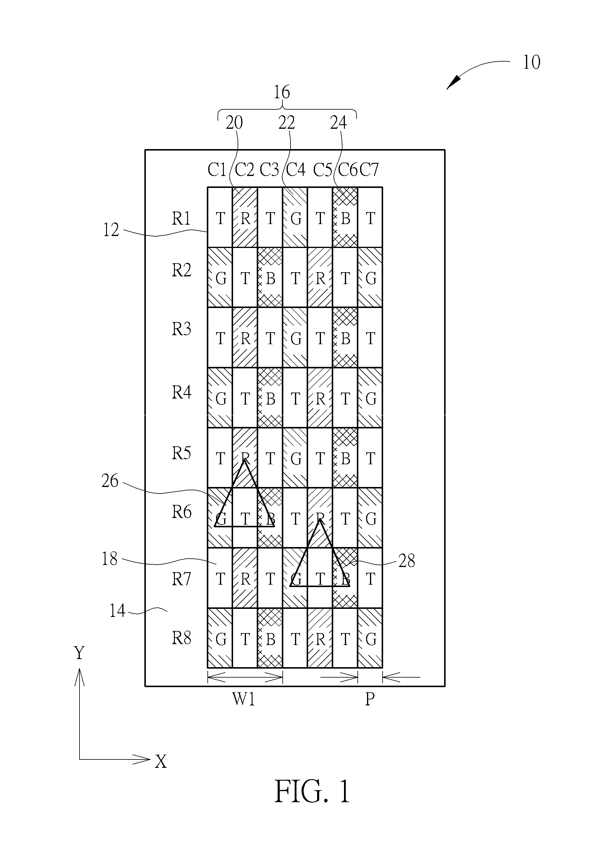
[0022]Referring to FIG. 1, FIG. 1 is a schematic top view of a transparent display panel in accordance with the first embodiment of the present embodiment. In the first embodiment, a transparent display panel 10 of the present invention optionally includes a display zone 12 and a peripheral zone 14. The display zone 12 includes a plurality of transparent regions 18 and a plurality of display regions 16 arranged alternately in the display zone 12, along a first direction (for example, Direction X or Direction Y as shown in FIG. 1), wherein the transparent regions 18 are shown as regions without shading in figures and have marked as “T”, and the display regions 16 are shown as regions with shading in figures. The display regions 16 refer to a sub-pixel part used for displaying images in a display panel. For instance, a switch circuit, a metal electrode, a light-emitting element or / and a color filter may be disposed in the display regions 16. One example of the light-emitting elements ...


PUM


Abstract

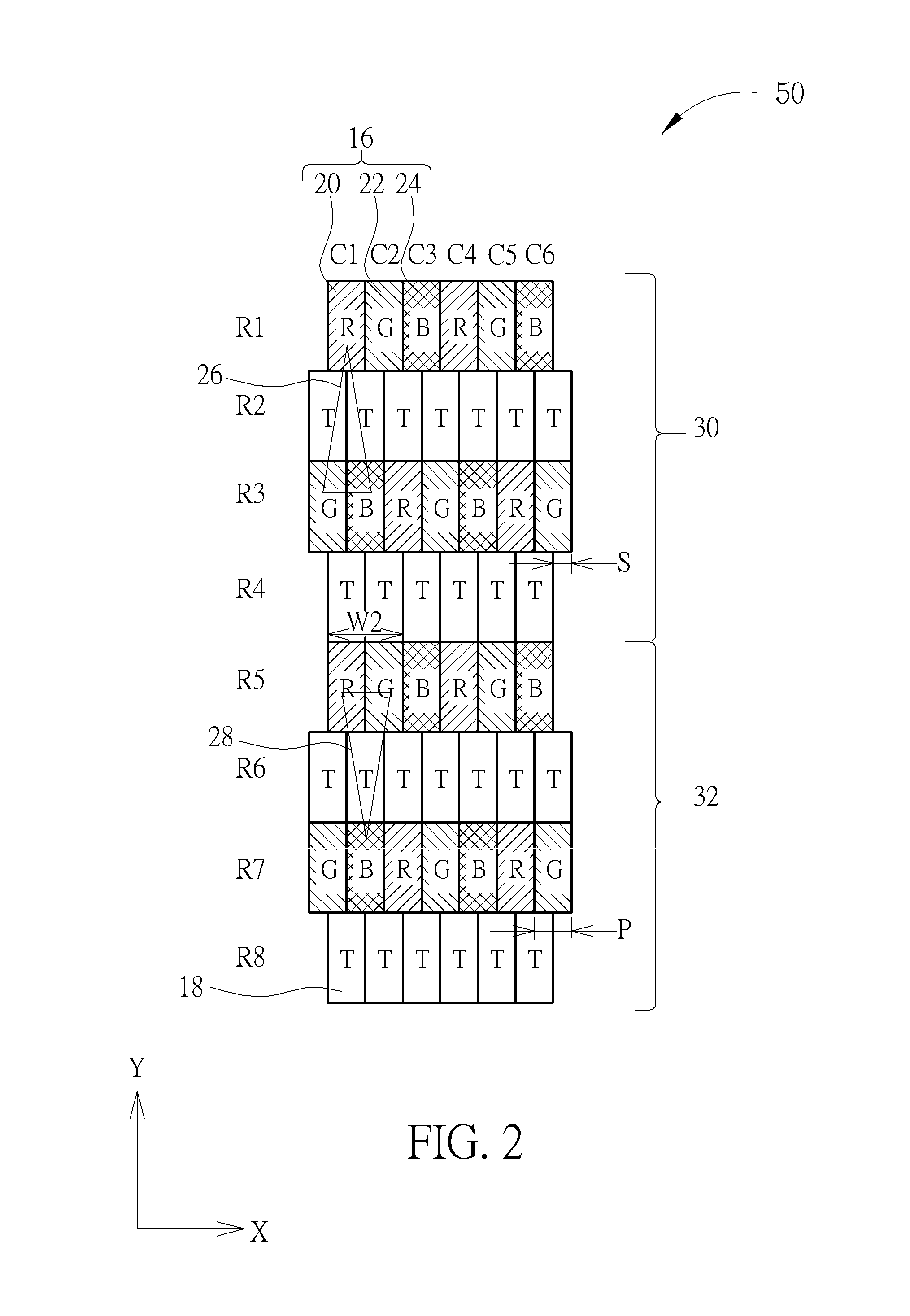
A transparent display device includes at least a first transparent display panel and a second transparent display panel, each of which has transparent regions and display regions. The arrangements of the transparent regions and display regions of the first transparent display panel and the second transparent display panel are opposite to each other. The transparent display device can apply a high transparency display mode or a lower transparency display mode by arranging the relative position of the first and second transparent display panels. In the lower transparency display mode, the first and second transparent display panels are at least partial overlapped with each other so as to display clear image with high definition.

Description

BACKGROUND OF THE INVENTION[0001]1. Field of the Invention[0002]The present invention relates to a transparent display device and a transparent display panel, and more particularly, to a transparent display device and a transparent display panel having transparent regions and display regions arranged in a specific arrangement so as to obtain enhanced display and transparent performance.[0003]2. Description of the Prior Art[0004]A transparent display generally refers to a display device which viewer can watch the image behind in the transparent state. The transparent display may be used in a showcase to display both a display image and materials behind the transparent display device. Many kinds of display panel with different technologies can be integrated with the transparent display device. Among the technologies, active matrix organic light emitting displays (AMOLEDs) have gained more and more attention due to further advantages of self-emitting light source, wide viewing angle, s...

Claims


Application Information

Patent Timeline
IPC IPC(8): G09F13/00
CPCG09F13/00G09F9/30G09F9/33H01L2924/0002H10K59/90H10K59/353H10K59/121H10K59/128H01L2924/00
Inventor LO, CHING-KAIYANG, HSUEH-YENCHEN, HSIEN-HUNGLIU, CHUN-HSIN
Owner AU OPTRONICS CORP
Learn More