
Laser processing apparatus carrying out control to reduce consumed power

Active Publication Date: 2014-10-16
FANUC LTD
View PDF5 Cites 0 Cited by
  • Summary
  • Abstract
  • Description
  • Claims
  • Application Information

AI Technical Summary

Benefits of technology

This patent text describes a gas laser processing apparatus that includes a laser oscillator, a laser processing machine, and a control part. The control part controls the laser oscillator and the laser processing machine based on a processing program. The technical effect of this invention is that it enables better energy efficiency and faster processing by automatically switching between a standard standby mode and an energy saving mode based on the preparatory operation and the output of the processing program, improving the overall efficiency of the gas laser processing apparatus.

Problems solved by technology

Therefore, there are the problems that a relatively long time is taken until the operation for canceling the energy saving mode is started, the energy saving mode becomes long in duration, and the amount of energy consumption increases.
However, the time of start of laser processing is not necessarily a constant one.
For example, if maintenance work or other non-routine work is carried out and the starting time of the laser processing is shifted, it is difficult to start the operation for ending the energy saving mode at a good timing.

Method used


Image

  • Laser processing apparatus carrying out control to reduce consumed power
  • Laser processing apparatus carrying out control to reduce consumed power
  • Laser processing apparatus carrying out control to reduce consumed power

Examples


Embodiment Construction

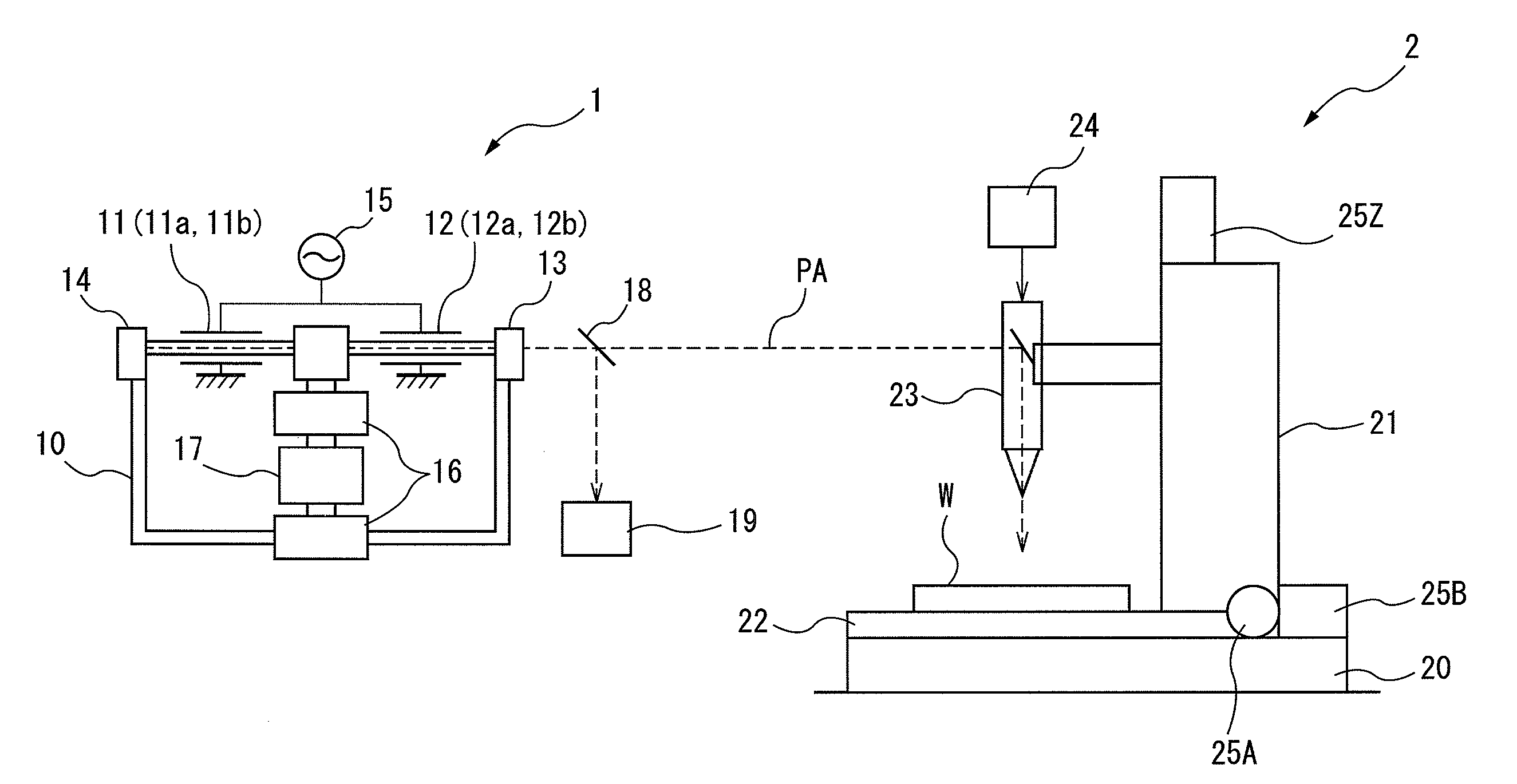
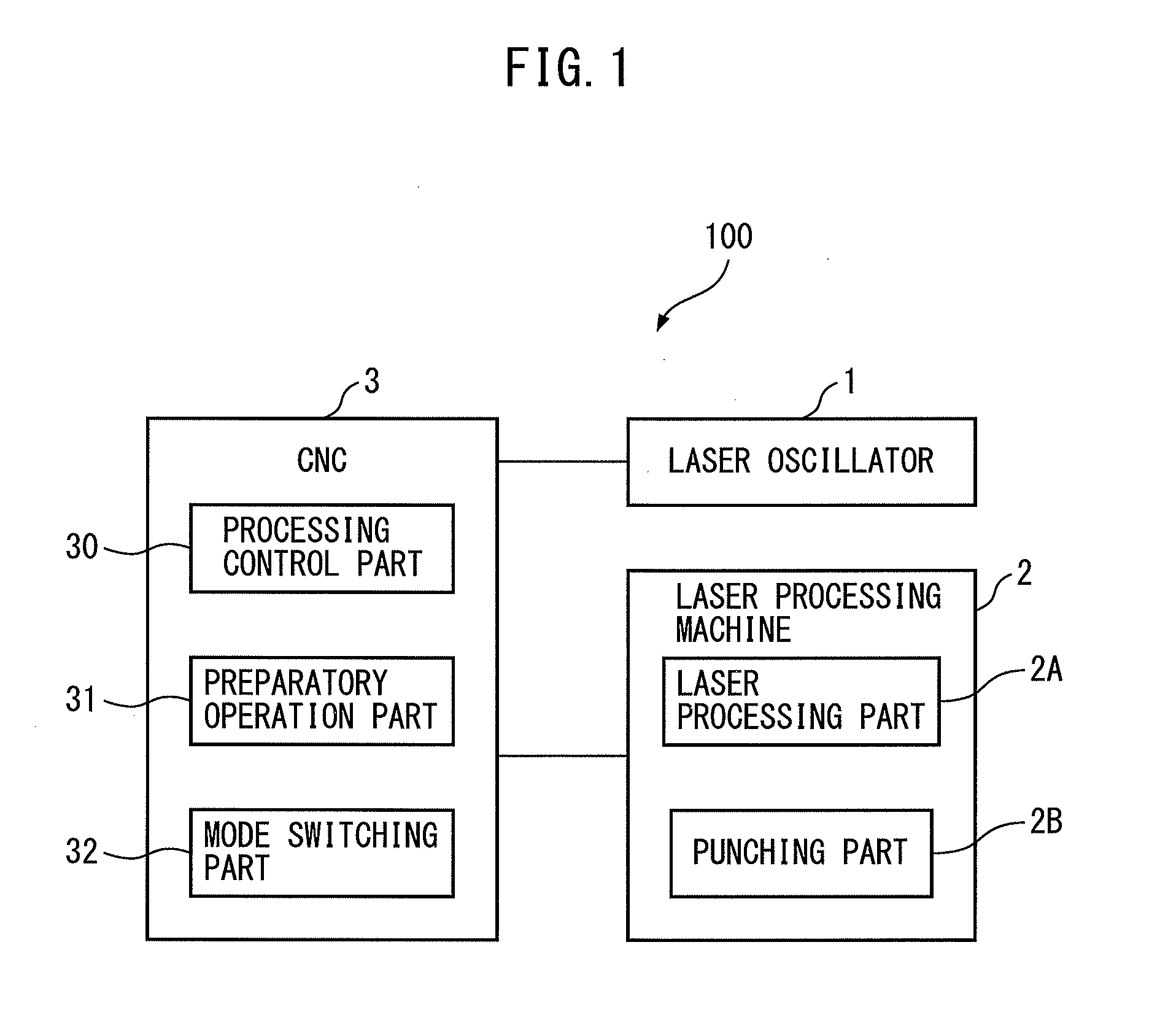
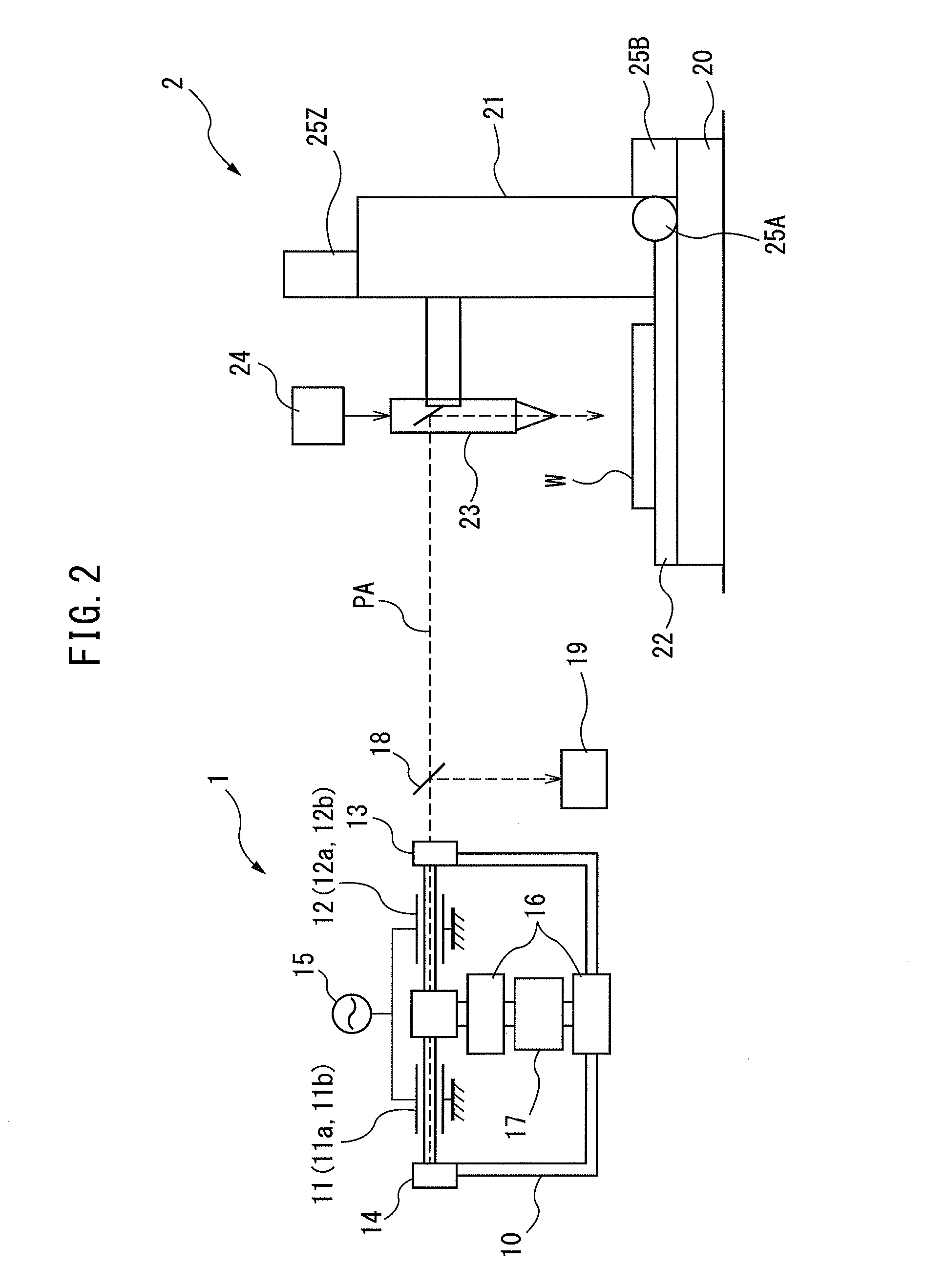
[0015]Below, referring to FIG. 1 to FIG. 6, an embodiment of a laser processing apparatus according to the present invention will be explained. FIG. 1 is a view which shows the overall configuration of a laser processing apparatus 100 according to an embodiment of the present invention. As shown in FIG. 1, the laser processing apparatus 100 has a laser oscillator 1 which generates laser light, a laser processing machine 2 which carries out laser processing by using the laser light which is output from the laser oscillator 1, and a control part 3 which controls the laser oscillator 1 and the laser processing machine 2 in accordance with a processing program.

[0016]The laser processing machine 2 is a composite processing machine which has a laser processing part 2A which carries out laser processing on a workpiece and a punching part 2B which punches holes in a workpiece by using a die. It can carry out laser processing and punching selectively and successively.

[0017]The control part 3...


PUM

PropertyMeasurementUnit
Poweraaaaaaaaaa
Energyaaaaaaaaaa
Processing propertiesaaaaaaaaaa

Abstract

A laser processing apparatus including a laser oscillator, a laser processing machine, and a control part controlling the laser oscillator and the laser processing machine. The control part includes a preparatory operation part controlling the laser processing machine so as to start a preparatory operation for the laser processing if a preparatory operation command is output and, a mode switching part switching an operating mode of the laser oscillator between a standard standby mode before carrying out the laser processing and an energy saving mode with less consumed power than the standard standby mode, and the mode switching part controls the discharge tube voltage so as to switch the operating mode to the energy saving mode before the preparatory operation command is output and to start a switching operation of the operating mode from the energy saving mode to the standard standby mode when the preparatory operation command is output.

Description

BACKGROUND OF THE INVENTION[0001]1. Field of the Invention[0002]The present invention relates to a laser processing apparatus which carries out a control to reduce the consumed power of a laser oscillator.[0003]2. Description of the Related Art[0004]In the past, there has been known a laser processing apparatus, which is set to a base discharge state with a low discharge voltage in a standard standby state before carrying out laser processing and which makes the base discharge stop and shifts to an energy saving mode when this base discharge state continues for a predetermined time so as to thereby keep down the consumption of energy in the standby period of a laser processing machine. This apparatus is, for example, described in Japanese Patent Unexamined Publication No. 2012-64636 (JP2012-064636A). In general, in this kind of laser processing apparatus, the operation to cancel the energy saving mode is started in a state where operations to select the pressure of the assist gas to...

Claims


Application Information

Patent Timeline
IPC IPC(8): H01S3/032
CPCH01S3/032B23K26/0884B23K26/14H01S3/09702H01S3/09713B23K26/0626B23K26/1435H01S3/104B23K26/70B23K26/00
Inventor MIYATA, RYUSUKE
Owner FANUC LTD
Learn More