Optical line monitoring system and method

a technology of optical line and monitoring system, applied in the field of optical line monitoring technique, can solve the problems of easy cutting of optical cables, low reliability of optical cables, inferior mechanical properties, etc., and achieve the effects of shortening the release time of optical lines, saving working hours and labor costs, and improving work efficiency

Active Publication Date: 2014-10-16
LG CABLE LTD (KR)
View PDF5 Cites 4 Cited by
  • Summary
  • Abstract
  • Description
  • Claims
  • Application Information

AI Technical Summary

Benefits of technology

[0014]The present disclosure may save working hours and labor costs required for monitoring optical lines by measuring and storing a distance of an optical channel service unit and automatically identifying an optical line of each pulse shown in an OTDR (Optical Time Domain Reflectometer) pulse pattern by using the stored distance information.
[0015]In addition, the present invention may shorten a release time of an optical line and improve work efficiency by accurately figuring out a path via which an abnormal pulse passes, recognizing the path as a path where a disorder occurs, and reporting the path to a manager.
[0016]In particular, the present disclosure allows a disorder of an optical line to be thoroughly verified by additionally inspecting a disorder of optical lines at identical or similar distances, which has not been detected through the comparison of an OTDR pulse pattern.

Problems solved by technology

However, optical cables have somewhat low reliability due to inferior mechanical properties in comparison to copper wires.
In other words, optical cables are easily cut in comparison to copper wires and when bent beyond a certain angle, does not allow for communication.
However, even though a disorder of a specific OTDR pulse signal may be checked by analyzing a plurality of OTDR pulses obtained through the optical measurement instrument, it is impossible to specify which individual optical line receives an individual OTDR pulse.
In other words, it is impossible to identify an optical channel service unit by which each of the plurality of OTDR pulses received through the optical measurement instrument is reflected.
However, this method requires manual work in order to check the length of an optical line, which also consumes a lot of labor costs.
Further, in the case a disorder occurs at a specific optical line among the plurality of optical lines via which the overlapping pulses pass, the optical line monitoring system may not accurately identify an optical line where the disorder occurs, which may delay actions to cope with the disorder.

Method used


Image

  • Optical line monitoring system and method
  • Optical line monitoring system and method
  • Optical line monitoring system and method

Examples


Embodiment Construction

[0024]The above objects, features and advantages will be more apparent through the following detailed description in relation to the accompanying drawings, and accordingly the technical spirit of the present disclosure can be easily implemented by those having ordinary skill in the art. In addition, if detailed description of a known technique relating to the present disclosure can make the substance of the present disclosure unnecessarily vague, the detailed description will be omitted. Hereinafter, a preferred embodiment of the present disclosure will be described in detail with reference to the accompanying drawings.

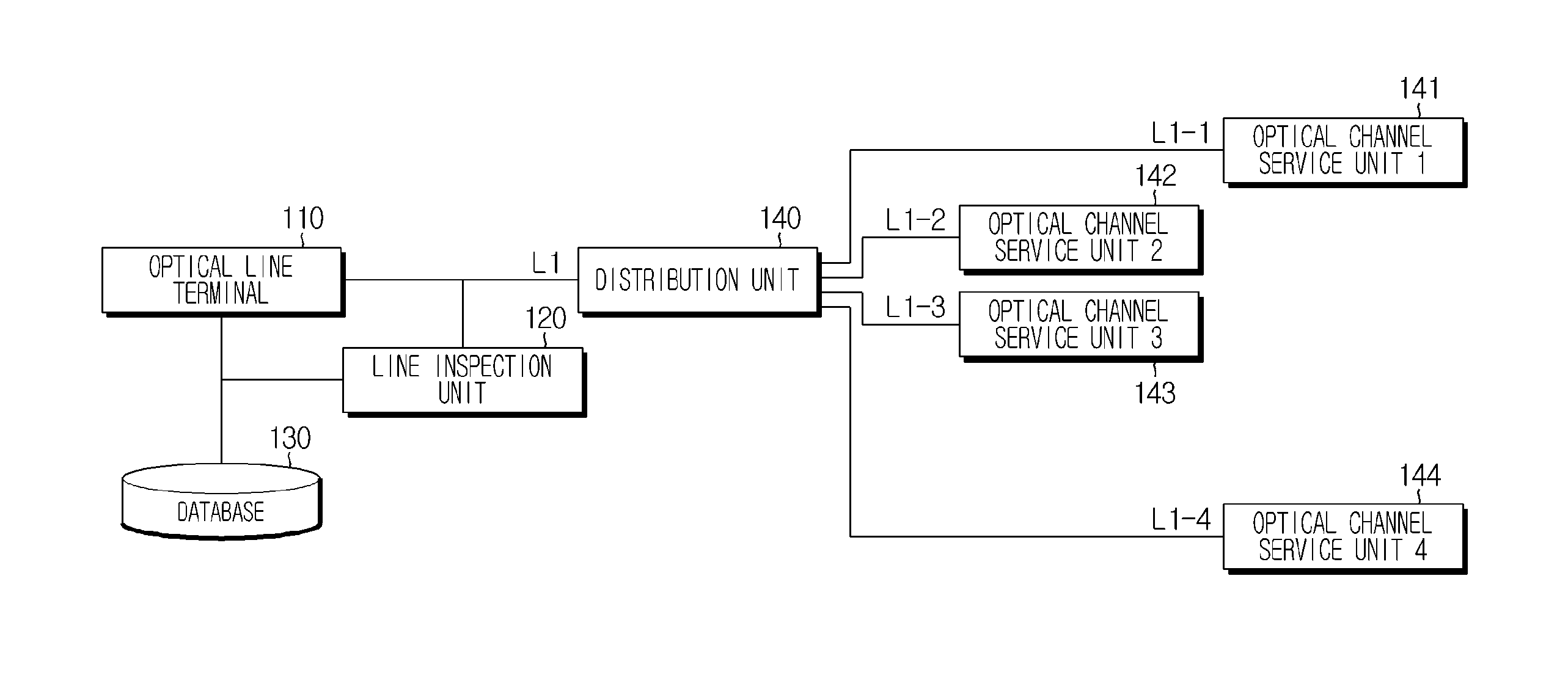
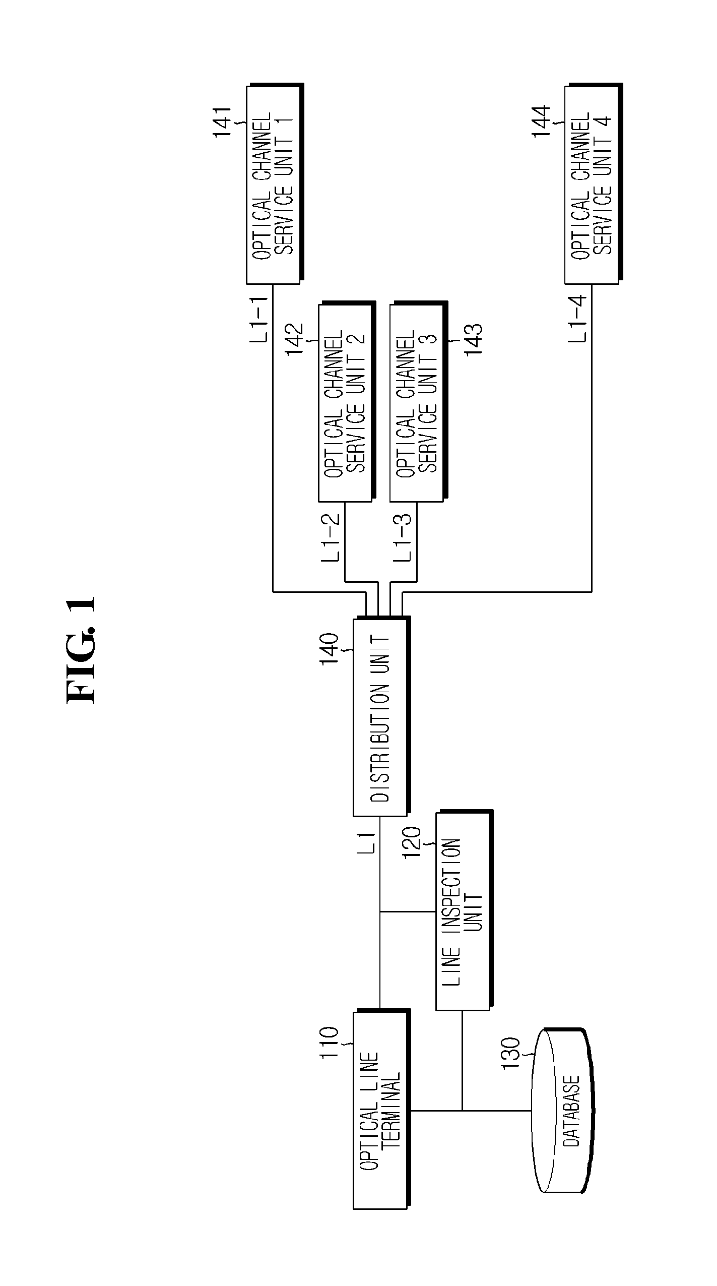
[0025]FIG. 1 is a diagram showing an optical line monitoring system according to an embodiment of the present disclosure.

[0026]As shown in FIG. 1, an optical line monitoring system according to the present disclosure includes an optical line terminal 110, a line inspection unit 120, a database 130, distribution unit 140 and optical channel service units 141, 142, 143,...


PUM


Abstract

Disclosed is an optical line monitoring system and method which detects an optical line where a disorder occurs, by using an OTDR (Optical Time Domain Reflectometer) pulse pattern with matching information. The optical line monitoring system generates and stores a reference OTDR pulse pattern matched with identification information of an optical channel service unit, and compares the matched reference OTDR pulse pattern with the OTDR pulse pattern collected at an inspection time to verify an optical line region where a disorder occurs.

Description

TECHNICAL FIELDCross-Reference to Related Application[0001]The present application claims priority to Korean Patent Application No. 10-2011-0103744 filed on Oct. 11, 2011 and Korean Patent Application No. 10-2012-0016530 filed on Feb. 17, 2012 in the Republic of Korea, the disclosures of which are incorporated herein by reference.[0002]The present disclosure relates to an optical line monitoring technique, and more particularly, to an optical line monitoring system and method which detects an optical line where a disorder occurs, by using an OTDR (Optical Time Domain Reflectometer) pulse pattern with matching information.BACKGROUND ART[0003]Optical cables are widely used for ultrahigh communication networks due to its low loss and large bandwidth in comparison to copper wires. However, optical cables have somewhat low reliability due to inferior mechanical properties in comparison to copper wires. In other words, optical cables are easily cut in comparison to copper wires and when b...

Claims


Application Information

Patent Timeline
Patent Type & Authority Applications(United States)
IPC IPC(8): H04B10/07
CPCH04B10/07H04B10/071
Inventor PARK, JI-SANGPARK, LAE-HYUKKIM, KI-YEULHAN, KWAN-HEEYANG, EUN-JEONG
Owner LG CABLE LTD (KR)
Why Eureka
Try Eureka