Assist grip attachment structure

a technology of attachment structure and grip, which is applied in the direction of monocoque construction, roof, vehicle arrangement, etc., can solve the problems of difficulty in achieving both the tensile load ensuring rigidity and the impact absorbing performance of absorbing the impact of pressing load, and achieves high rigidity, easy adjustment of the degree of weakness, and high rigidity.

Inactive Publication Date: 2014-10-23
TOYODA IRON WORKS CO LTD
View PDF7 Cites 3 Cited by
  • Summary
  • Abstract
  • Description
  • Claims
  • Application Information

AI Technical Summary

Benefits of technology

[0009]In the assist grip attachment structure as described above, the low-rigidity portion and the high-rigidity portion are formed in the vehicle body-side attachment portion to which the assist grip is attached, and when the pressing load is applied to the assist grip, the pressing-side engagement portion fixedly fitted to the assist grip presses and deforms the low-rigidity portion from the inside of the vehicle cabin, so that an impact of the pressing load is appropriately absorbed through the deformation of the low-rigidity portion. When the tensile load is applied to the assist grip, the tension-side engagement portion fixedly fitted to the assist grip is engaged with the high-rigidity portion from the side opposite to the inside of the vehicle cabin, so that the assist grip is supported with high rigidity by the high-rigidity portion. In this case, because the support rigidity with which the assist grip is supported against the tensile load is ensured by the rigidity of the high-rigidity portion, and the impact absorbing performance of absorbing an impact of the pressing load is appropriately set by adjusting the degree of weakness (ease of deformation) of the low-rigidity portion, it is possible to easily achieve both securing of the support rigidity against the tensile load and the impact absorbing performance of absorbing an impact of the pressing load.
[0010]In the second aspect of the invention, the attachment plate portion has the engagement hole, in which the attachment end portion of the assist grip is inserted from the inside of the vehicle cabin and is engaged, and the cuts are formed around the engagement hole and along the engagement hole, the portion located inward of the cuts is used as the low-rigidity portion, and the portion located outward of the cuts is used as the high-rigidity portion. Therefore, by appropriately setting the position, the depth, the length, or the like of the cuts, it is possible to easily adjust the degree of weakness of the low-rigidity portion, that is, the impact absorbing performance of absorbing an impact of the pressing load without affecting the support rigidity against the tensile load.
[0011]In the third aspect of the invention, the clip having a hat-shaped section is provided, and the attachment end portion of the assist grip is attached to the vehicle body-side attachment portion via the clip. By just inserting the pair of engagement lugs into the engagement hole from the protruded portion having a hat-shaped section while elastically deforming the pair of engagement lugs, the clip is assembled to the attachment plate portion, and the attachment end portion of the assist grip is attached to the vehicle body-side attachment portion via the clip. Moreover, in the attachment state, the inner peripheral edge portion around the engagement hole of the attachment plate portion is located between the flange portions, which serve as the pressing-side engagement portions, and the engagement lugs, which serve as the tension-side engagement portions. When the pressing load is applied to the assist grip, the flange portions are engaged with the low-rigidity portion from the inside of the vehicle cabin, so that an impact of the pressing load is appropriately absorbed through the deformation of the low-rigidity portion. On the other hand, when the tensile load is applied to the assist grip, the engagement lugs are engaged with the high-rigidity portion from the side opposite to the inside of the vehicle cabin, so that the assist grip is supported with high rigidity. That is, in the third aspect of the invention, it is possible to easily attach the attachment end portion of the assist grip to the vehicle body-side attachment portion via the clip. Further, the clip is provided with the flange portions and the engagement lugs, which serve as the pressing-side engagement portions and the tension-side engagement portions, respectively. In addition, the low-rigidity portion is formed in the inner peripheral edge portion around the engagement hole of the attachment plate portion by the cuts. Provision of the flange portions and the engagement lugs in addition to formation of the low-rigidity portion makes it possible to easily and inexpensively obtain an attachment structure that makes it possible to appropriately achieve both the impact absorbing performance of absorbing an impact of the pressing load and the support rigidity against the tensile load.

Problems solved by technology

However, in such a conventional assist grip attachment structure, because an impact of a pressing load is absorbed through bending deformation of the attachment plate portion, there is a problem that it is difficult to achieve both ensuring of support rigidity against a tensile load and impact absorbing performance of absorbing an impact of a pressing load.

Method used


Image

  • Assist grip attachment structure
  • Assist grip attachment structure
  • Assist grip attachment structure

Examples


embodiment

[0027]Hereinafter, an embodiment of the invention will be described in detail with reference to the drawings.

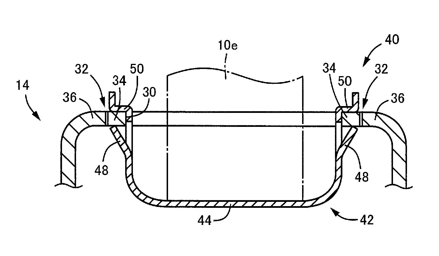
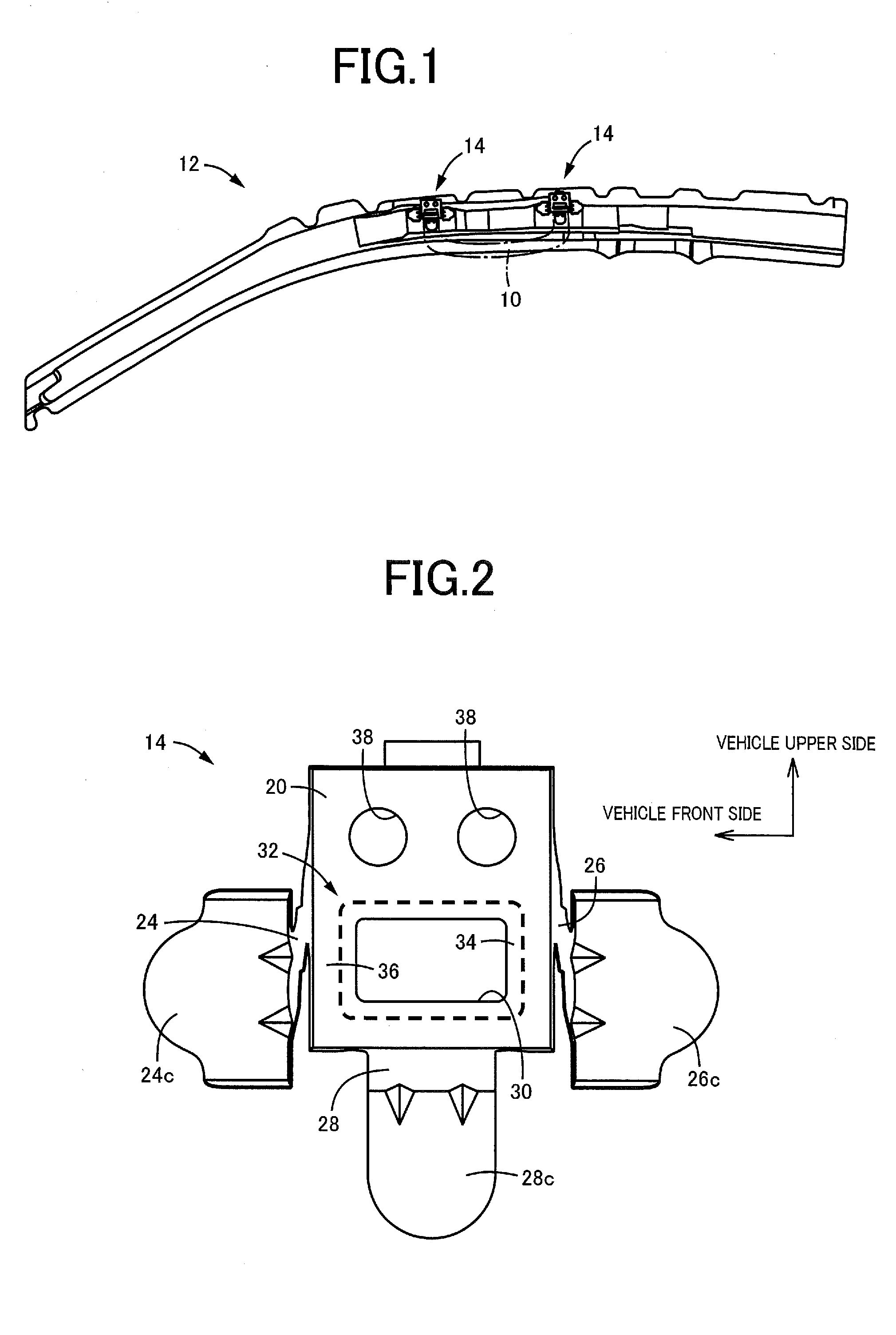
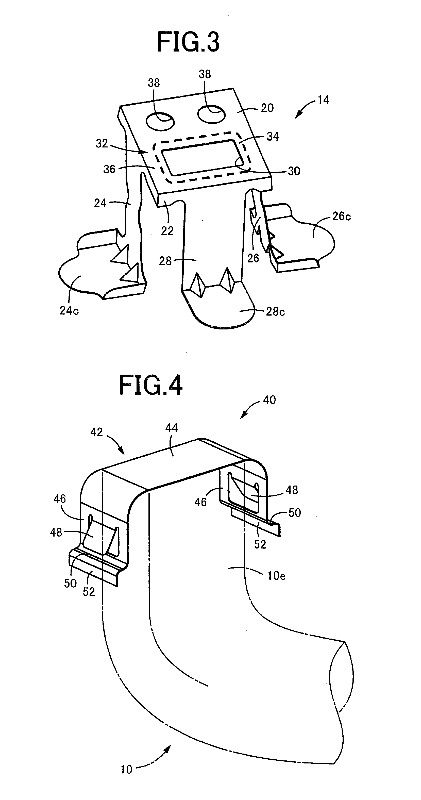
[0028]FIG. 1 is a front view illustrating an example of a roof side rail inner member 12 to which an assist grip 10 is attached with the use of an attachment structure according to the invention. The roof side rail inner member 12 is disposed above a driver's seat on the right side of a vehicle, and grip attachment brackets 14 are fixedly fitted respectively to a pair of attachment portions to which a pair of attachment end portions 10e (see FIG. 4, for example) of a flat U-shaped assist grip 10 are respectively attached. Each grip attachment bracket 14 corresponds to a vehicle body-side attachment portion.

[0029]FIG. 2 is a front view illustrating the grip attachment bracket 14 alone as viewed from substantially the same direction as the direction from which the components in FIG. 1 are viewed. FIG. 3 is a perspective view of the grip attachment bracket 14. The grip attachmen...


PUM


Abstract

An assist grip attachment structure in which an assist grip is attached to a vehicle body-side attachment portion, the assist grip is supported with prescribed rigidity by the vehicle body-side attachment portion when a tensile load in a direction in which the assist grip is pulled toward an inside of a vehicle cabin is applied to the assist grip, and an impact of a pressing load is absorbed through deformation of the vehicle body-side attachment portion when the pressing load is applied to the assist grip from the inside of the vehicle cabin.

Description

TECHNICAL FIELD[0001]The invention relates to an assist grip attachment structure, and more specifically to an attachment structure in which an assist grip is supported with prescribed rigidity against a tensile load and an impact of a pressing load is appropriately absorbed through deformation.BACKGROUND ART[0002]There has been proposed an assist grip attachment structure in which an assist grip is attached to a vehicle body-side attachment portion, the assist grip is supported with prescribed rigidity by the vehicle body-side attachment portion when a tensile load in a direction in which the assist grip is pulled toward the inside of a vehicle cabin is applied to the assist grip, and an impact of a pressing load is absorbed through deformation of the vehicle body-side attachment portion when the pressing load is applied to the assist grip from the inside of the vehicle cabin. An example of such an assist grip attachment structure is a device described in Patent Document 1, in whic...

Claims


Application Information

Patent Timeline
Patent Type & Authority Applications(United States)
IPC IPC(8): B60N3/02
CPCB60N3/02B60N3/026
Inventor CHIKADA, SHIMPEI
Owner TOYODA IRON WORKS CO LTD
Why Eureka
Try Eureka