Broadband sensor location selection using convex optimization in very large scale arrays

a convex optimization and array technology, applied in the direction of transducer casings/cabinets/supports, instruments, electrical transducers, etc., can solve the problem of complex acoustic scene understanding

Active Publication Date: 2014-10-23
UNIV OF MARYLAND +1
View PDF9 Cites 61 Cited by
  • Summary
  • Abstract
  • Description
  • Claims
  • Application Information

AI Technical Summary

Benefits of technology

[0017]In accordance with another aspect of the present invention, a system to monitor an acoustic target in a target location in a space monitored by N microphones is provided, comprising: a memory enabled to store data including instructions, a processor, enabled to retrieve and execute instructions from the memory to perform the steps: accepting a number D equal to or greater than 2 and smaller than N; accepting a number of L locations in the space, wherein each location in the L locations is treated as

Problems solved by technology

Acoustic scene understanding is challenging for complex environments with e.g, multiple sources, correlated sources, non-punctual sources, mixed far field and near field sources, reflections, shadowing from objects.
Though methods exist to focus a plurality of micr

Method used


Image

  • Broadband sensor location selection using convex optimization in very large scale arrays
  • Broadband sensor location selection using convex optimization in very large scale arrays
  • Broadband sensor location selection using convex optimization in very large scale arrays

Examples


Embodiment Construction

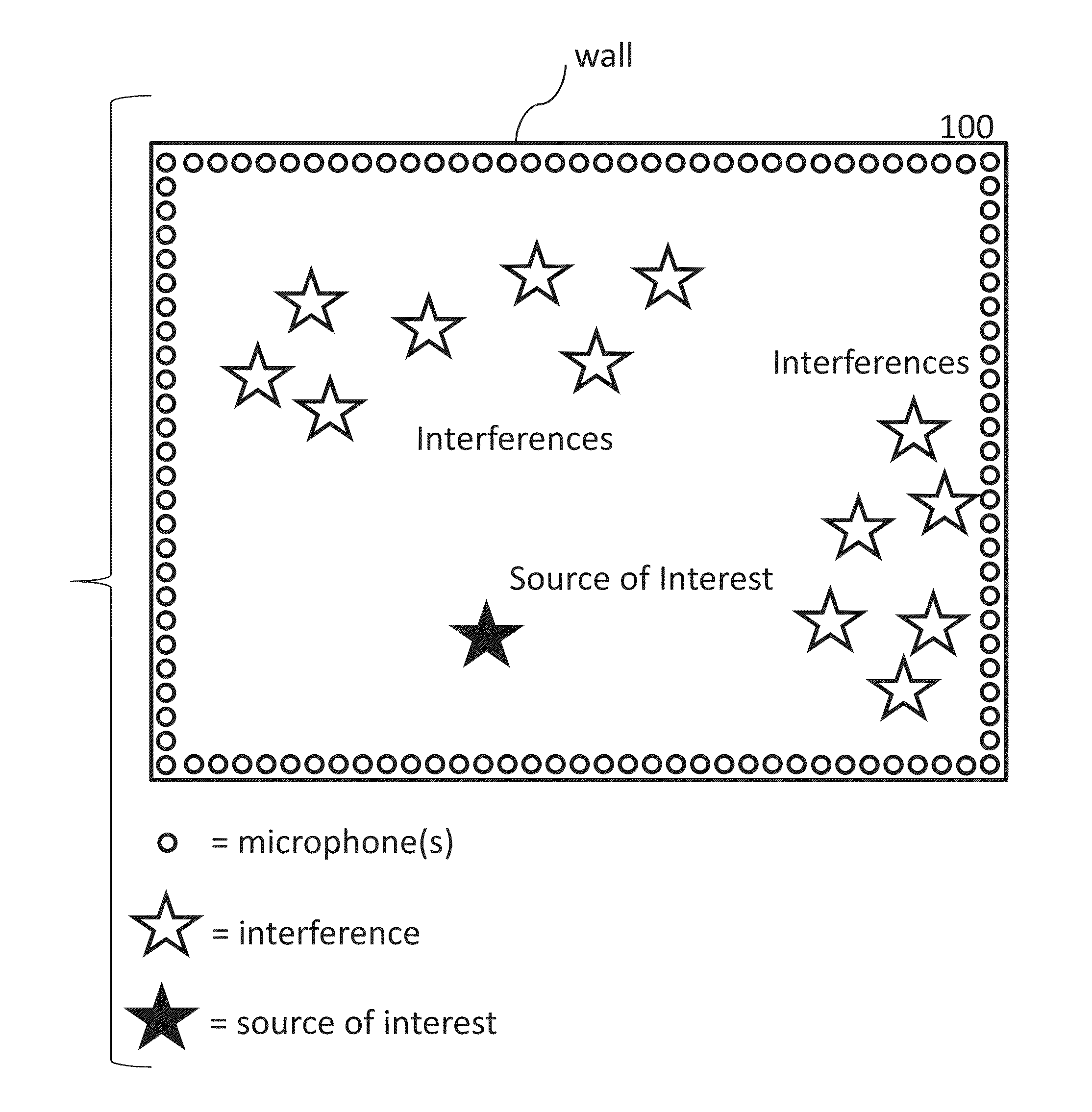
[0039]One issue that is addressed herein in accordance with an aspect of the present invention is acoustic scene understanding by applying an ultra large array of microphones. The subject of acoustic scene understanding has been addressed in a different way in commonly owned U.S. Pat. No. 7,149,691 to Balan et al., issued on Dec. 12, 2006, which is incorporated herein by reference, wherein ultra large microphones are not applied.

[0040]In the current approach a number of high level processes are assumed:

(1) Localization of acoustic sources in the environment, representing both targets and interferences, and further source classification;

(2) Tracking of features of the sources or even separation of target sources of interest;

(3) Mapping the environment configuration such as location of walls and determination of room layout and obstacles.

[0041]A target herein is a source of interest. A target may have a specific location or certain acoustic properties that makes it of interest. An int...


PUM


Abstract

Systems and methods are provided to determine a subset of D microphones in a set of N microphones on a perimeter of a space to monitor a target location. The space is divided into L interference locations. An equation is solved to determine microphone weights for the N microphones by minimizing the maximum gain for signals related to the target location and interference locations, further optimized over an l1 penalty by applying a Lagrange multiplier to an l1 norm of the microphone weights in a manner that determines a set of D non-zero microphones weights and a set of (N−D) microphone weights that are zero or close to zero. Microphone weights are determined for at least 2 different frequencies.

Description

CROSS REFERENCE TO RELATED APPLICATIONS[0001]The present application is a continuation-in-part and claims the benefit of U.S. patent application Ser. No. 13 / 644,432 filed on Oct. 4, 2012 which is incorporated herein by reference in its entirety. The present application also claims the benefit of U.S. Provisional Patent Application Ser. No. 61 / 888,550 filed on Oct. 9, 2013, which is incorporated by reference herein in its entirety.GOVERNMENT INTERESTS[0002]One or more aspects described herein were supported by the National Science Foundation (NSF) under contract number DMS-1109498. The U.S. Government may have certain rights in the claimed inventions.BACKGROUND OF THE INVENTION[0003]The present invention relates generally to locating, extracting and tracking acoustic sources in an acoustic environment and mapping of the acoustic environment by adaptively employing a very large number of microphones.[0004]Acoustic scene understanding is challenging for complex environments with e.g, m...

Claims


Application Information

Patent Timeline
IPC IPC(8): H04R3/00
CPCH04R3/005G10L25/48G10L2021/02166H04M3/568H04M2203/509H04R1/406H04R25/405H04R25/407H04R2225/41H04R2225/43H04R2430/03H04R2430/23
Inventor ROSCA, JUSTINIANCLAUSSEN, HEIKOBALAN, RADU VICTORLAI, YENMING
Owner UNIV OF MARYLAND
Why Eureka
Try Eureka