Rolling bearing device

a technology of rolling bearings and rollers, which is applied in the direction of rolling contact bearings, rotary bearings, shafts and bearings, etc., can solve the problems of poor lubrication, low efficiency, and poor lubrication of certain rolling bearing devices, and achieve the effect of increasing service life and exuding base oil from a lubrican

Inactive Publication Date: 2014-10-23
JTEKT CORP
View PDF0 Cites 1 Cited by
  • Summary
  • Abstract
  • Description
  • Claims
  • Application Information

AI Technical Summary

Benefits of technology

[0008]An object of the present invention is to provide a rolling bearing device in which efficiency, with which base oil exudes from a lubricant, is improved so that the base oil can be continuously supplied into an inner portion of a rolling bearing for a long period of time and thus, a service life is increased.

Problems solved by technology

In the machine tool requiring high-speed rotation performance, it is necessary to continue to uninterruptedly supply the base oil into an inner portion of the rolling bearing for a long period of time.
When a long period of time had elapsed from the start of the test, poor lubrication was detected in a certain rolling bearing device.
That is, it is presumed that the base oil contained in the lubricant inside the lubricant reservoir was supplied into the inner portion of the rolling bearing with low efficiency, and as a result, the poor lubrication had occurred.
Further, the reason is considered to be that the base oil exuded from the lubricant with low efficiency.
However, in this case, there is a possibility that a structure of the lubricant reservoir becomes complicated since it is necessary to provide a sealing structure for containing the base oil in a leak-proof manner.

Method used


Image

  • Rolling bearing device
  • Rolling bearing device
  • Rolling bearing device

Examples


first embodiment

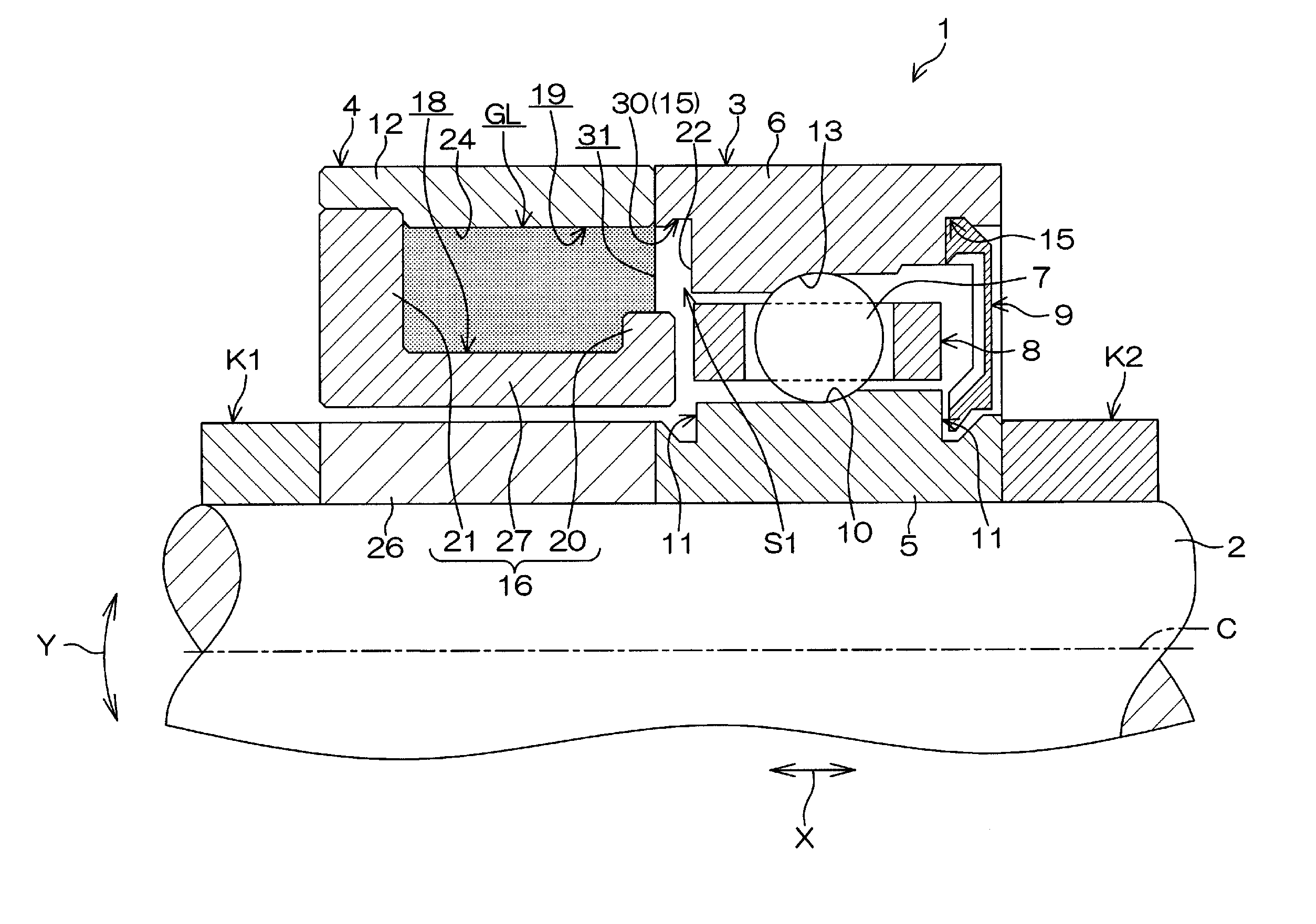
[0016]Hereinafter, embodiments of the present invention will be described in detail with reference to the accompanying drawings. FIG. 1 is a sectional view of a rolling bearing device 1 according to the present invention. For example, the rolling bearing device 1 is a device that supports a main shaft (shaft supported by a rolling bearing) 2 of a machine tool. The rolling bearing device 1 includes a rolling bearing 3 and a lubricant storage member (member adjacent to a fixed side) 4. The rolling bearing 3 is constituted by an angular contact ball bearing. The lubricant storage member 4 is disposed adjacent to the rolling bearing 3.

[0017]As illustrated in FIG. 1, the rolling bearing 3 includes an inner ring 5, an outer ring (fixed side of inner and outer rings) 6, rolling elements 7, a cylindrical cage 8 and a seal 9. An inner periphery of the inner ring 5 is fitted to an outer periphery of the main shaft 2. An outer periphery of the outer ring 6 is fitted to an inner periphery of a ...

second embodiment

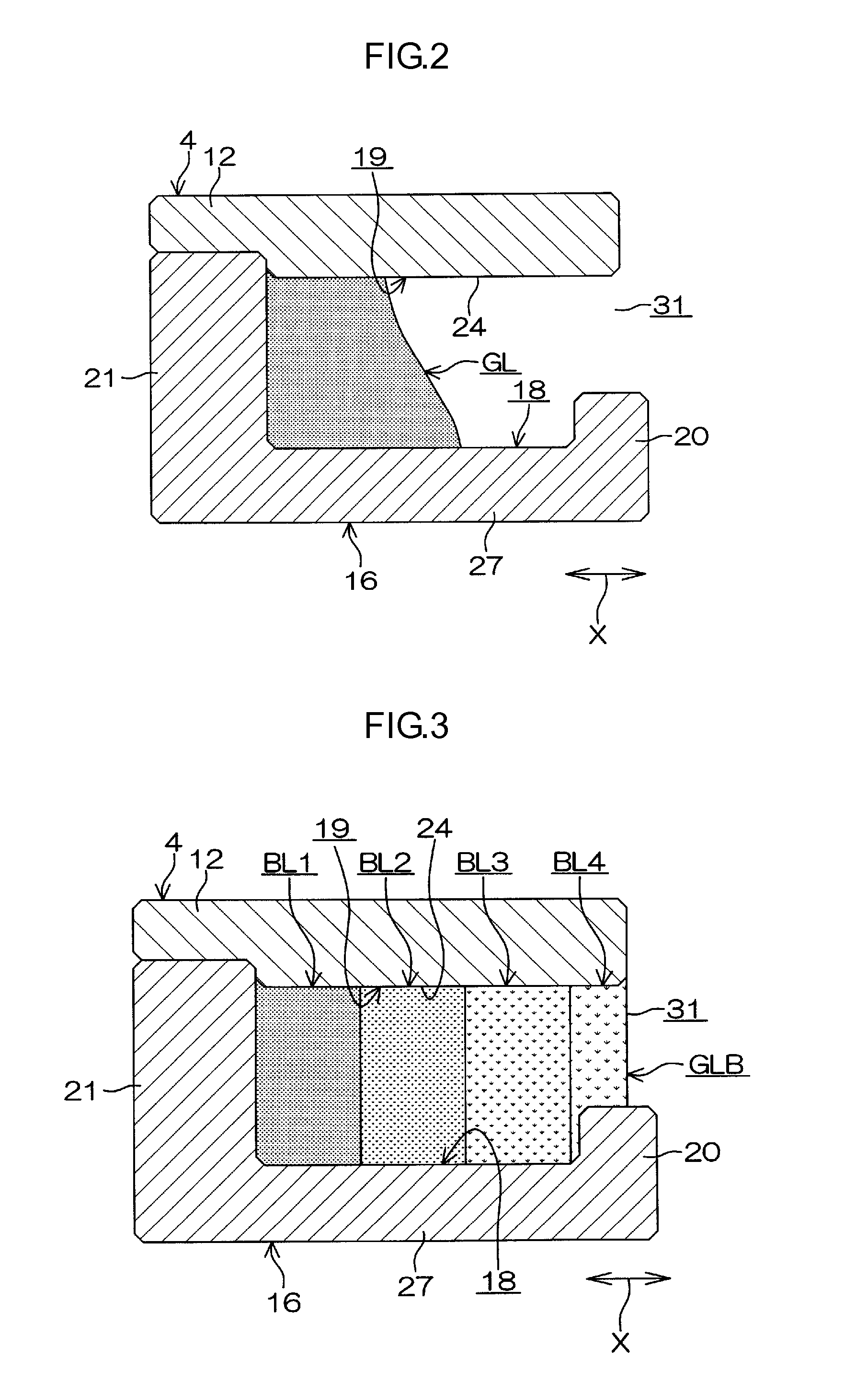
[0033]The feature of the second embodiment is that in a lubricant GLB disposed in the lubricant reservoir 19, the base oil concentration varies with respect to the axial direction X. Specifically, in the lubricant GLB, the base oil concentration increases in a direction toward a side away from the opening 31 (i.e., toward the left side in FIG. 3) with respect to the axial direction X. More specifically, the lubricant GLB is divided into, for example, four lubricant blocks that are BL1, BL2, BL3, BL4 disposed in the this order from the side opposite to the rolling bearing 3 (left side in FIG. 3) with respect to the axial direction X. Four lubricant blocks BL1, BL2, BL3, BL4 have base oil concentrations different from each another. For example, the base oil concentration of the lubricant block BL1 is 50% by weight, and the base oil concentration of the lubricant block BL2 is 40% by weight to 30% by weight. For example, the base oil concentration of the lubricant block BL3 is 30% by we...


PUM


Abstract

A rolling bearing device includes a rolling bearing, and a lubricant reservoir that is formed in an outer ring spacer. A lubricant containing base oil, a gelling agent and water is disposed so as to be contained in the lubricant reservoir. The lubricant has a uniform base oil concentration. The base oil concentration is 40% by weight to 50% by weight.

Description

INCORPORATION BY REFERENCE[0001]The disclosure of Japanese Patent Application No. 2013-088592 filed on Apr. 19, 2013 including the specification, drawings and abstract, is incorporated herein by reference in its entirety.BACKGROUND OF THE INVENTION[0002]1. Field of the Invention[0003]The invention relates to a rolling bearing device.[0004]2. Description of Related Art[0005]Conventionally, there has been known a rolling bearing device which is used for a spindle of a machine tool, and which includes a lubricant-inclusion type lubrication mechanism. The lubricant-inclusion type rolling bearing device is described, for example, in Japanese Patent Application Publication No. 2006-234072 (JP2006-234072A). The rolling bearing device includes a rolling bearing and a lubricant reservoir-formed component having a lubricant reservoir disposed inside thereof. The lubricant reservoir-formed component is disposed adjacent to an outer ring. A lubricant is disposed so as to be contained in the lub...

Claims


Application Information

Patent Timeline
Patent Type & Authority Applications(United States)
IPC IPC(8): F16C33/66
CPCF16C33/6688F16C33/6655F16C33/664F16C33/6696F16C19/163
Inventor MISADA, YASUHARU
Owner JTEKT CORP
Why Eureka
Try Eureka