Image forming apparatus

Active Publication Date: 2014-10-23
RICOH KK
View PDF2 Cites 0 Cited by
  • Summary
  • Abstract
  • Description
  • Claims
  • Application Information

AI Technical Summary

Benefits of technology

The present invention provides an image forming apparatus that can reduce displacement between drive units. The apparatus includes a pair of side walls, a driven unit, a drive unit, and a reinforcing member. The reinforcing member connects the side walls and allows for the driven unit to move while maintaining its position relative to the drive unit. This results in an apparatus that can maintain optimal performance even when subjected to deformation.

Problems solved by technology

However, with such an arrangement, any impact to the apparatus during shipping may cause the side walls to deform even temporarily, thereby displacing the units or at worst dislodging them altogether.
However, to completely prevent deformation of the apparatus body is difficult even with a reinforcing member.

Method used


Image

  • Image forming apparatus
  • Image forming apparatus
  • Image forming apparatus

Examples


Embodiment Construction

[0022]Hereinafter, the present invention is described referring to accompanying drawings. In each figure illustrating the present invention, a part or component having the same function or shape is applied with the same reference numeral, and once explained, a duplicated description thereof is omitted.

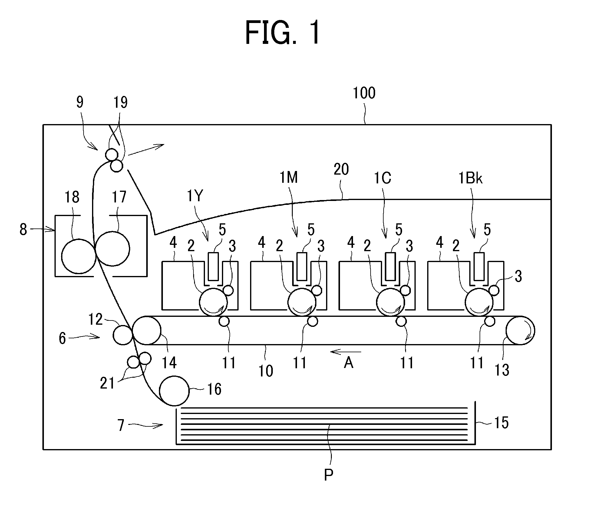
[0023]FIG. 1 is a schematic view of an image forming apparatus illustrating an embodiment of the present invention. First, with reference to FIG. 1, a whole structure and operation of an image forming apparatus according to an embodiment of the present invention is described.

[0024]As illustrated in FIG. 1, four process units 1Y, 1M, 1C, and 1Bk each as an image forming unit are detachably attached to an apparatus body 100. Each of the process units 1Y, 1M, 1C, and 1Bk has the same structure except that each includes a different color of developer such as yellow (Y), magenta (My, cyan (C), and black (Bk) that corresponds to RGB color separation component of a color image.

[0025]Specifica...


PUM


Abstract

An image forming apparatus includes a pair of side walls disposed opposite each other; a driven unit supported between the side walls; a drive unit with drive transmission gears attached to one of the side walls and drives the driven unit; and a reinforcing member connecting the pair of side walls. One end of the reinforcing member is attached to the side wall opposite the other side wall to which the drive unit is attached and the other end is attached to the drive unit. The driven unit is an image forming unit including at least an image carrier. The image carrier includes a rotary shaft, both lateral ends of which are supported by the pair of side walls. A gear portion engaging the drive transmission gears of the drive unit is disposed on one end of the rotary shaft of the image carrier.

Description

CROSS-REFERENCE TO RELATED APPLICATION[0001]The present application claims priority pursuant to 35 U.S.C. §119(a) from Japanese patent application number 2013-087388, filed on Apr. 18, 2013, the entire disclosure of which is incorporated by reference herein.BACKGROUND[0002]1. Technical Field[0003]The present invention relates to an image forming apparatus such as a printer, a copier, a facsimile machine, or a multi-function apparatus having one or more capabilities of the above devices.[0004]2. Related Art[0005]Image forming apparatuses are known in which units such as image forming units and drive units are supported between a pair of side walls that form part of the body of the apparatus. In this type of image forming apparatus, the image forming units, drive units, and the like are installed in the apparatus so as to reduce the overall size of the package during shipping.[0006]However, with such an arrangement, any impact to the apparatus during shipping may cause the side walls ...

Claims


Application Information

Patent Timeline
IPC IPC(8): G03G15/00
CPCG03G15/757G03G21/1619G03G21/1647G03G2215/0141
Inventor HASHIMOTO, HARUOYAMAZAKI, KOZO
Owner RICOH KK
Why Eureka
Try Eureka