R-t-b rare earth sintered magnet and method of manufacturing the same
Active Publication Date: 2014-10-23
TDK CORPARATION
View PDF8 Cites 11 Cited by
Summary
Abstract
Description
Claims
Application Information
AI Technical Summary
This helps you quickly interpret patents by identifying the three key elements:
Problems solved by technology
Method used
Benefits of technology
Benefits of technology
[0035]Since the method of manufacturing an R-T-B rare earth sintered magnet according to the above aspect of the invention includes a sintering process of disposing the compact of the powder of the first alloy and the second alloy (alloy mater
Problems solved by technology
However, heavy rare earth element can be mined only in the limited place.
Therefore, when a large amount of heavy rare earth elements is used, the balance between the de
Method used
Image
Click on the blue label to locate the original text in one second.
Reading with bidirectional positioning of images and text.
Examples
Example
Test Examples 1 to 12 and 51 to 54
[0118]A Nd metal (having a purity of 99 wt % or greater), a Pr metal (having a purity of 99 wt % or greater), a Dy metal (having a purity of 99 wt % or greater), a Co metal (having a purity of 99 wt % or greater), ferroboron (Fe 80 wt %, B 20 wt %), a lump of iron (having a purity of 99 wt % or greater), a Ga metal (having a purity of 99 wt % or greater), an Al metal (having a purity of 99 wt % or greater), a Cu metal (having a purity of 99 wt %), and a Zr metal (having a purity of 99 wt % or greater) were weighed to provide compositions of alloys 1 to 8 shown in Table 1 and were put into an alumina crucible. “TRE” shown in Table 1 represents a total of rare earth elements. In addition, the composition “bal.” of Fe means the balance. C, O, and N shown in Table 1 are inevitable impurities contained in the raw materials.
[0119]Thereafter, the alumina crucible was put into a high frequency vacuum induction furnace. The atmosphere in the furnace was repl...
Example
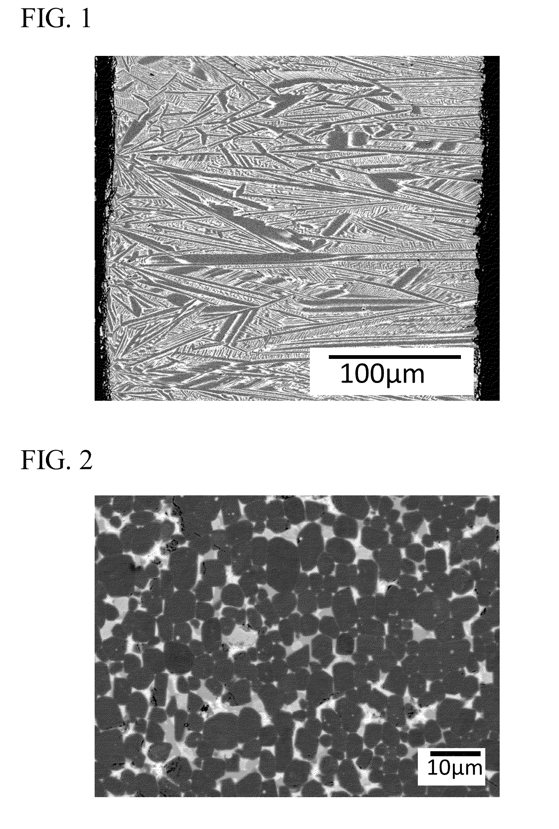
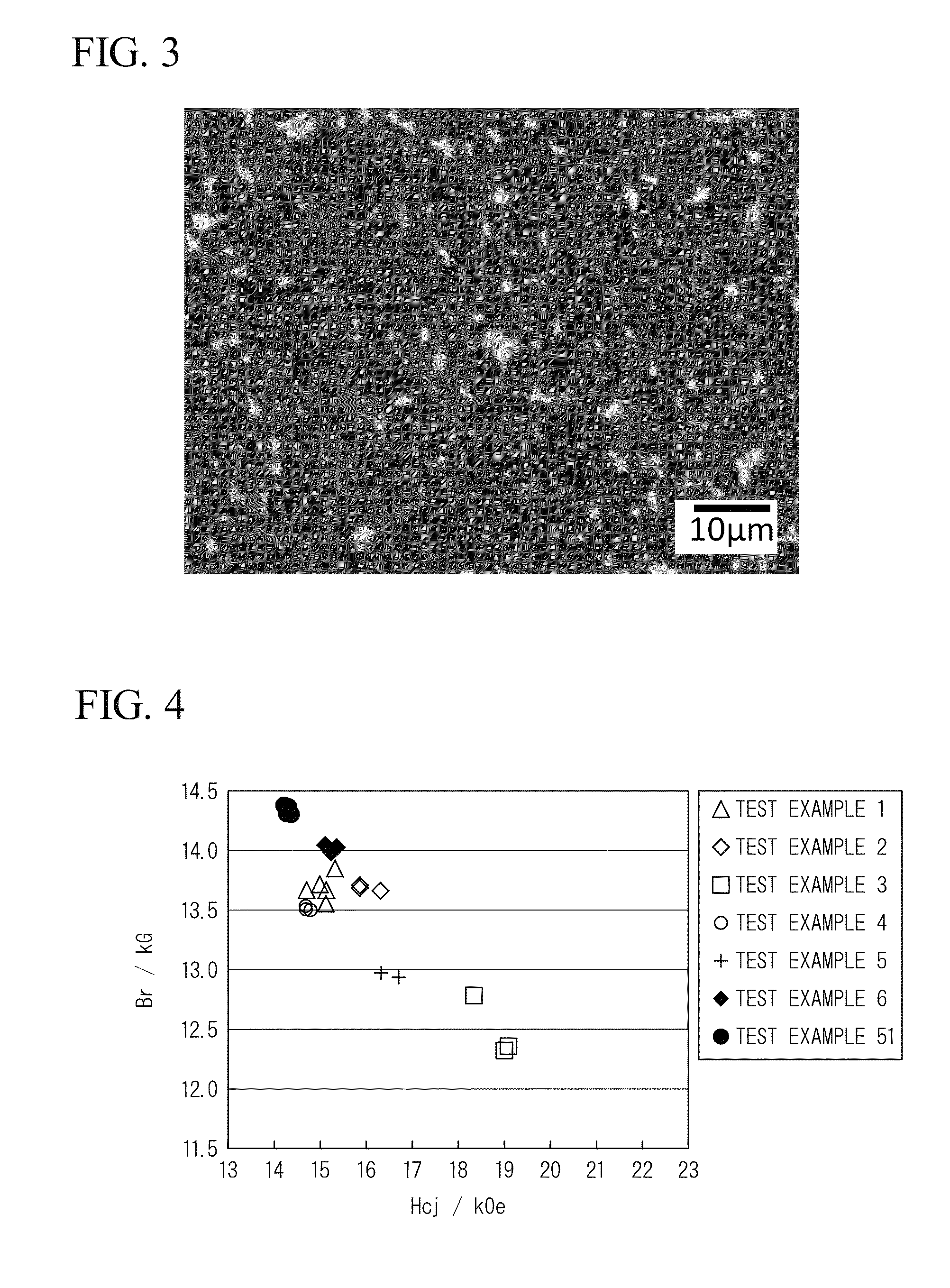
[0131]FIG. 2 is a microphotograph obtained by observing the R-T-B magnet of Test Example 3 through a backscattered electron image, and FIG. 3 is a microphotograph obtained by observing the R-T-B magnet of Test Example 51 through a backscattered electron image. The direction of the axis of easy magnetization (C axis) of the R-T-B magnets shown in FIGS. 2 and 3 corresponds to a horizontal direction in FIGS. 2 and 3.
[0132]As shown in FIG. 2, in the R-T-B magnet of Test Example 3, main phase grains were isolated by a grain boundary phase surrounding the main phase grains.
[0133]However, in the R-T-B magnet of Test Example 51 shown in FIG. 3, the contours of main phase grains were not clear and a plurality of main phase grains were in contact with each other, compared to the R-T-B magnet of Test Example 3.
[0134]In addition, the compositions of the R-T-B magnets of Test Examples 1 to 12 and 51 to 54 were measured using an inductively coupled plasma (ICP) apparatus. The results thereof are ...
Example
[0135]As shown in Tables 1 to 3, in the R-T-B magnet of Test Example 1 in which the alloy 1 was used in both of the compact and the alloy material, TRE is greater than the R-T-B magnet of Test Example 51 in which the compact made from the alloy 1 without using an alloy material was sintered.
PUM
Property
Measurement
Unit
Temperature
aaaaa
aaaaa
Temperature
aaaaa
aaaaa
Length
aaaaa
aaaaa
Abstract
A method of manufacturing an R-T-B rare earth sintered magnet includes a process of disposing and sintering a compact of a first alloy powder and an alloy material of a second alloy in a chamber of a sintering furnace. The first alloy consists of R which represents a rare earth element, T which represents a transition metal essentially containing Fe, a metal element M which represents Al and/or Ga, B, Cu, and inevitable impurities. The first alloy contains 11 at % to 17 at % of R, 4.5 at % to 6 at % of B, 0 at % to 1.6 at % of M, and T as the balance, and Dy content in all of the rare earth elements is 0 at % to 29 at %. The second alloy consists of R which represents a rare earth element, T which represents a transition metal essentially containing Fe, a metal element M which represents Al and/or Ga, B, Cu, and inevitable impurities. The second alloy contains 11 at % to 20 at % of R, 4.5 at % to 6 at % of B, and 0 at % to 1.6 at % of M, and T as the balance, and Dy content in all of the rare earth elements is 0 at % to 29 at %.
Description
BACKGROUND OF THE INVENTION[0001]1. Field of the Invention[0002]The present invention relates to an R-T-B rare earth sintered magnet and a method of manufacturing the R-T-B rare earth sintered magnet, and particularly, to a method of manufacturing an R-T-B rare earth sintered magnet having excellent magnetic properties.[0003]Priority is claimed on Japanese Patent Application No. 2013-089744, filed on Apr. 22, 2013, and Japanese Patent Application No. 2013-151073, filed on Jul. 19, 2013, the contents of which are incorporated herein by reference.[0004]2. Description of Related Art[0005]Hitherto, R-T-B rare earth sintered magnets (hereinafter, may be referred to as “R-T-B magnet”) have been used in voice coil motors of hard disk drives and motors for engines of hybrid automobiles and electric automobiles.[0006]In general, in R-T-B magnets, R is Nd, a part of which is replaced by other rare earth elements such as Pr, Dy, and Tb. T is Fe, a part of which is replaced by other transition ...
Claims
Application Information
Patent Timeline
Application Date:The date an application was filed.
Publication Date:The date a patent or application was officially published.
First Publication Date:The earliest publication date of a patent with the same application number.
Issue Date:Publication date of the patent grant document.
PCT Entry Date:The Entry date of PCT National Phase.
Estimated Expiry Date:The statutory expiry date of a patent right according to the Patent Law, and it is the longest term of protection that the patent right can achieve without the termination of the patent right due to other reasons(Term extension factor has been taken into account ).
Invalid Date:Actual expiry date is based on effective date or publication date of legal transaction data of invalid patent.

