
Method to prevent interference and detect collision between mechanical members

Active Publication Date: 2014-10-23
GIMA
View PDF0 Cites 7 Cited by
  • Summary
  • Abstract
  • Description
  • Claims
  • Application Information

AI Technical Summary

Benefits of technology

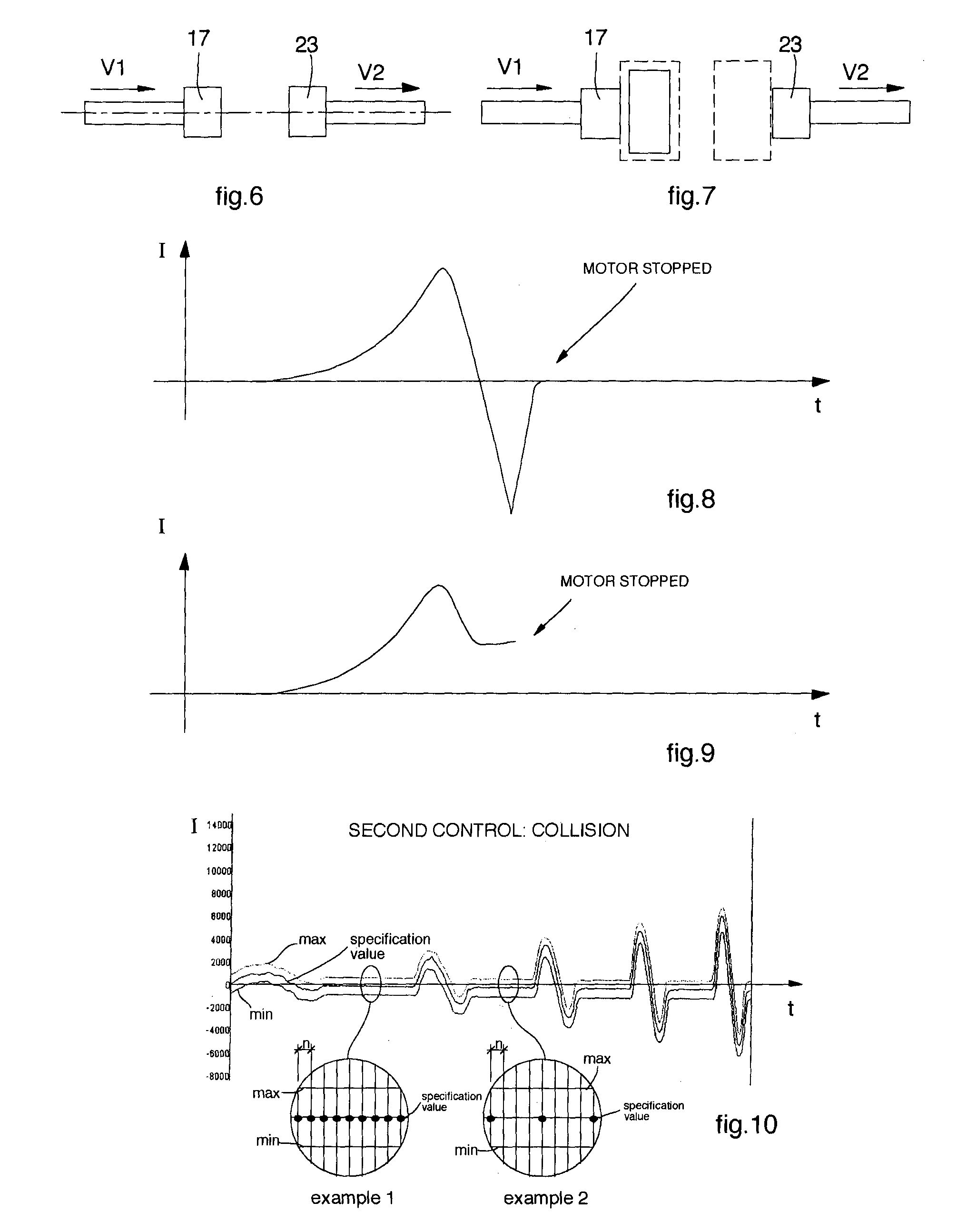
The present invention provides a method for preventing interference and detecting collisions in a system with two operating units. The method involves continuously or periodically detecting the position of the motor shafts and dividing the cycle into sub-phases to compare the actual current with a reference current and limit the current to a window of acceptability. This allows for the detection of collisions in both acceleration and deceleration, as well as sudden changes in mechanics inertia. The management program of the two operating units provides all the physical conditions and situations that can lead to interference or collisions, and if no control is made of the interference, the collisions control detects it and proceeds with the blocking, thus preventing possible breakages.

Problems solved by technology

One disadvantage of such work units is that, in the event of blockages, yielding, wear or other anomalies, a phase displacement is created between the point-by-point position assumed and the theoretical or desired position of the mechanical members.

Method used


Image

  • Method to prevent interference and detect collision between mechanical members
  • Method to prevent interference and detect collision between mechanical members
  • Method to prevent interference and detect collision between mechanical members

Examples


Embodiment Construction

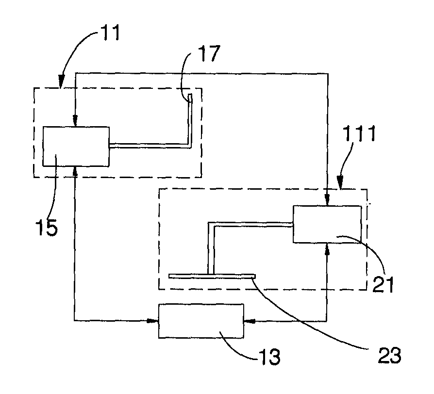
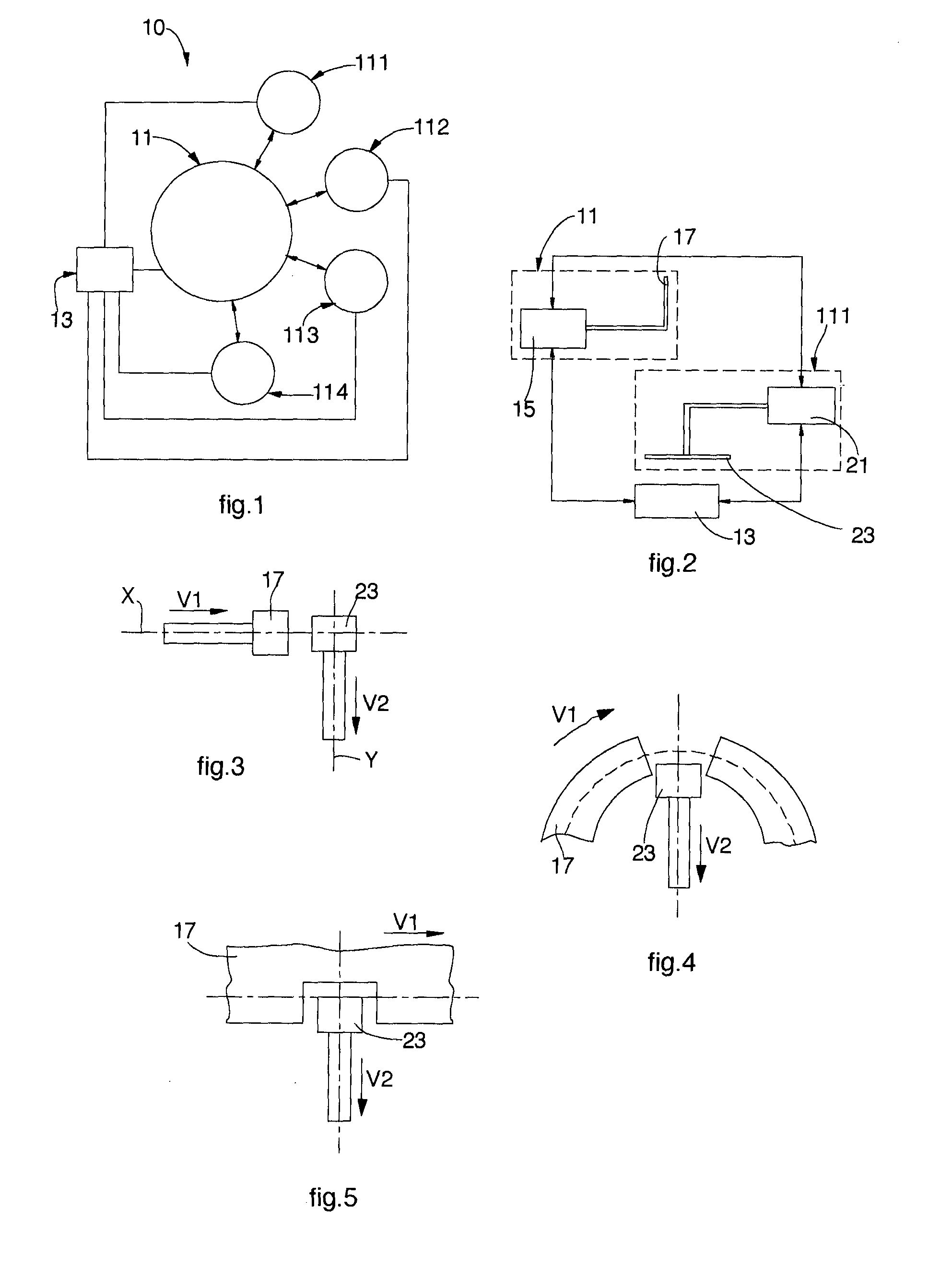
[0042]With reference to FIG. 1, the method to control interference and / or to control collisions is applied to an automation unit 10 which comprises an operating unit 11 that cooperates with a plurality of operating units 111, 112, 113, 114. The operating units 11, 111, 112, 113, 114 are governed by a management and control unit 13. As we said, the two methods can operate in different formulations, that is, they can:[0043]operate in distinct and autonomous mode[0044]operate in an integrated but independent mode[0045]operate in integrated and substantially sequential mode.

[0046]With reference to FIG. 2, the operating unit 11 has a position detector so that it does not allow phase displacements or drifts, and an electric motor 15.

[0047]The shaft of the electric motor 15 is connected to a mechanical member 17. In the same way, another operating unit 111 is associated with its own position detector and an electric motor 21 directly connected to a mechanical member 23. The mechanical memb...


PUM


Abstract

Method to control the interference and / or collision between mechanical members of at least two operating or one operating unit with respect to fixed positions. At least one operating unit is associated with a position detector or with a position simulator, and is equipped with an electric which drives a mechanical member. The method is managed by a management and control unit. The control of the operating units occurs in two phases, verifying point-by-point the position of the mechanical member as a function of the current dynamics and the braking or acceleration times and spaces (first phase), and verifying the intensity of point-by-point current supplied to at least one electric motor (second phase).

Description

FIELD OF THE INVENTION[0001]The present invention concerns a method particularly suitable to control the interference and / or collision of mechanical members moved by electric motors, which for example can be the brushless type. The invention also concerns the connected system operating in connection with a substantially sequential logic.BACKGROUND OF THE INVENTION[0002]Automation units are known, comprising one or more operating units comprising a drive member, a mechanical member, a position detector mean, that is, an entity that simulates mathematically the position of the drive shaft. The mechanical members of the operating units are therefore normally moved by electric motors, and are connected to the shaft of the latter directly or by means of kinematic reduction units. The motors, commanded by a central management and control unit, drive the operating units in pre-established cycles and in a coordinated manner, to obtain a desired interaction, for example so that they interact...

Claims


Application Information

Patent Timeline
IPC IPC(8): G05B19/4061
CPCG05B19/4061G05B2219/49157G05B2219/37632G05B2219/37622G05B19/0425
Inventor MONARI, IURIDRAGHETTI, FIORENZO
Owner GIMA
Learn More