High temperature resistance testing device for glass panel of integrated cooker

A glass panel and testing device technology, which is applied in the direction of measuring device, testing material strength by applying repetitive force/pulsation force, and transmittance measurement, etc., can solve the function loss of integrated stove, the glass panel is not strong in high temperature resistance, and cannot be clearly reflected Integrated stove and other issues

Active Publication Date: 2022-08-05
浙江雅士林智能家居有限公司
View PDF10 Cites 0 Cited by
  • Summary
  • Abstract
  • Description
  • Claims
  • Application Information

AI Technical Summary

Problems solved by technology

[0005] Aiming at the deficiencies of the prior art, the present invention provides a high temperature resistance testing device for the glass panel of an integrated stove, which is equipped with testing the strength of the glass panel against sharp objects, testing the strength of the glass panel against the impact of large-area objects, and testing the resistance of the glass panel to The advantages of high temperature capability and testing the light transmittance of the glass panel solve the problem that sharp objects may damage the glass panel, collisions between large-area objects and the glass panel may cause loss of function of the integrated stove, and glass panels may suffer from poor high temperature resistance. The problem that the user's health is damaged when the user uses it and the glass panel with poor light transmission cannot clearly reflect the functions of the integrated stove

Method used


Image

  • High temperature resistance testing device for glass panel of integrated cooker
  • High temperature resistance testing device for glass panel of integrated cooker
  • High temperature resistance testing device for glass panel of integrated cooker

Examples


Embodiment 1

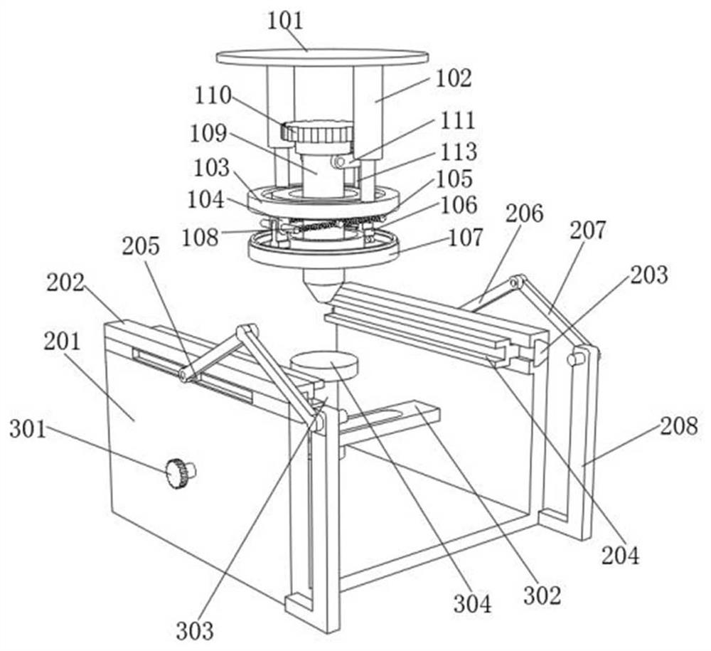
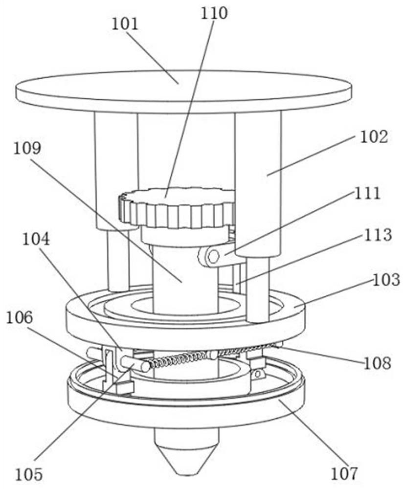
[0035] see Figure 1 to Figure 6 , a high temperature resistance test device for an integrated stove glass panel, comprising a top plate 101, the top plate 101 defines the position of the telescopic rod 102, two telescopic rods 102 are fixedly connected below the top plate 101, the size of the telescopic rod 102 is the same as that of the top plate 101 to the top plate 103 The distances between the two telescopic rods 102 are matched, and the two telescopic rods 102 are axially symmetrically distributed with the follower 302 as the axis of symmetry. The telescopic rods 102 rise or fall, which can drive other structures such as the top plate 103, the chassis 107 and the rotating column 109. contact with the glass panel to test the impact resistance of the glass panel;

[0036] A top plate 103 is fixedly connected to one end of the two telescopic rods 102 away from the top plate 101 , the top plate 103 is provided with an annular groove whose size matches the bottom of the limit...

Embodiment 2

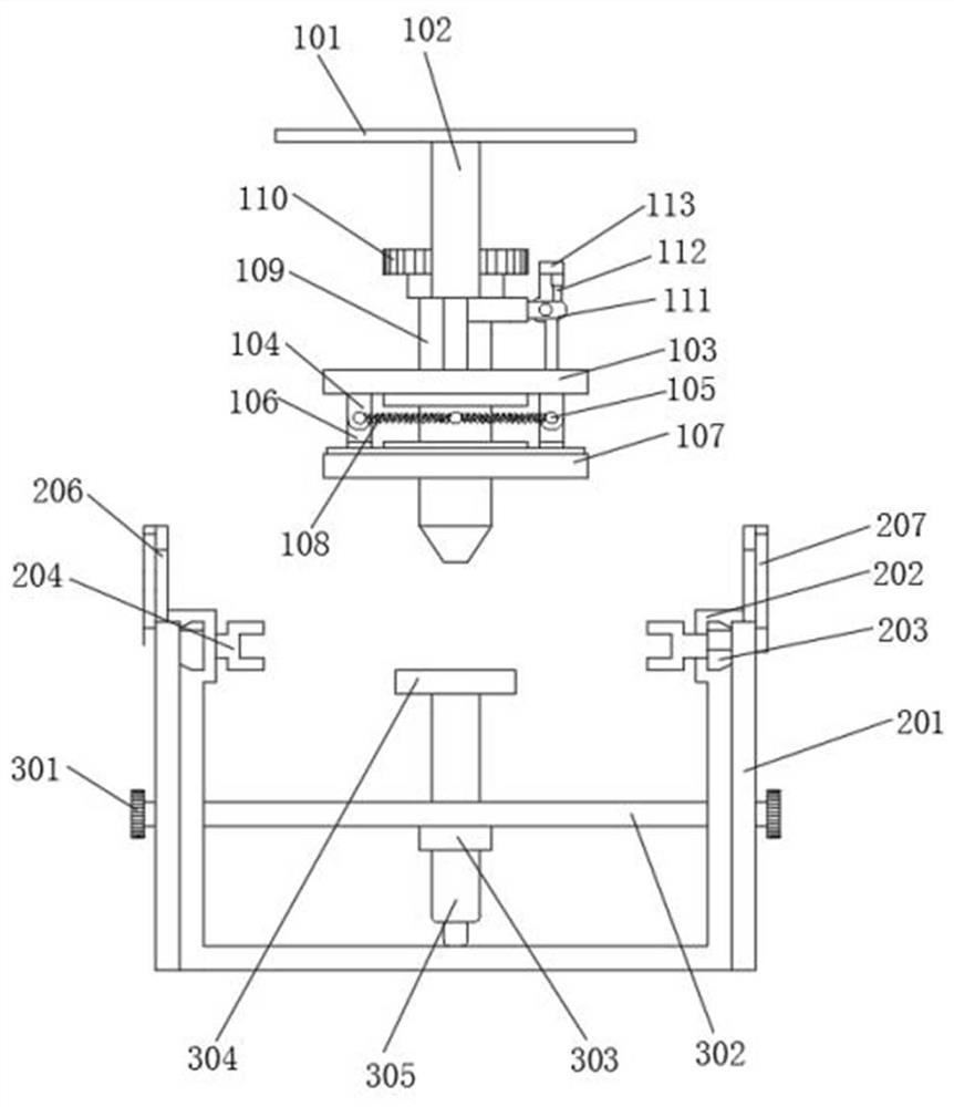
[0045] see Figure 7 to Figure 10 , a high temperature resistance test device for an integrated stove glass panel, including a frame 201, the frame 201 defines the positions of the trapezoidal block 203 and the follower 302 and other structures; the frame 201 is provided above with two limiting blocks 202, the limiting blocks 202 and the A through hole with a size matching the trapezoidal block 203 is formed between the frames 201, and the limiting block 202 defines the position of the trapezoidal block 203;

[0046] Two opposite trapezoidal blocks 203 are arranged below the two limiting blocks 202. The trapezoidal block 203 is provided with a groove whose size matches the sliding block 205 on the side close to the connecting rod 1 206. The trapezoidal block 203 connects the clamping block 204 and the sliding block. 205. When the trapezoidal block 203 starts to move under the action of the sliding block 205, the position of the clamping block 204 is changed; The opposite side...

Embodiment 3

[0050] see Figure 7 to Figure 10 , a high-temperature resistance test device for an integrated stove glass panel, including a runner 301, and the position of the follower 302 can be adjusted by rotating the runner 301; A through hole with a size matching the connection block 303 is opened, the size of the follower 302 is matched with the frame 201, and the follower 302 is deflected under the driving of the runner 301, thereby changing the position of the heating plate 304 and the spotlight 305;

[0051] The inside of the follower 302 is provided with a connecting block 303. The size of the connecting block 303 matches the through hole opened in the follower 302. The two ends of the follower 302 are hinged to the two sides of the frame 201 respectively. The position of the heating plate 304 and the spotlight 305; the heating plate 304 is fixedly connected to the top of the connection block 303, and the heating plate 304 contacts the glass panel when it continues to heat up, an...


PUM


Abstract

The invention relates to the technical field of glass panel testing, and discloses an integrated cooker glass panel high temperature resistance testing device which comprises a top plate and a frame, the lower portion of the top plate is fixedly connected with two telescopic rods, the size of the telescopic rods is matched with the distance between the top plate and a top disc, and the two telescopic rods are distributed in an axial symmetry mode with a driven piece as the symmetry axis; the ends, away from the top plate, of the two telescopic rods are fixedly connected with top discs, and annular grooves matched with the bottoms of the limiting blocks in size are formed in the tops of the top discs. According to the high-temperature-resistant testing device for the glass panel of the integrated cooker, an operator puts a cut glass panel into a clamping block, the glass panel is fixed by the clamping block, and at the moment, the hinged end of a second connecting rod and a fixed block is rotated, so that the second connecting rod begins to move, the second connecting rod is hinged to a first connecting rod, and the end, away from the second connecting rod, of the first connecting rod is hinged to a sliding block; the size of the sliding block is matched with that of the groove formed in the trapezoidal block, so that the second connecting rod drives the first connecting rod to start to move when starting to move.

Description

technical field [0001] The invention relates to the technical field of glass panel testing, in particular to a high temperature resistance testing device for a glass panel of an integrated stove. Background technique [0002] Integrated stove is a kitchen appliance that integrates various functions such as range hood, gas stove, disinfection cabinet, storage cabinet, etc. It is also called environmental protection stove or integrated environmental protection stove. Environmental protection and other advantages, the integrated stove is composed of a stove body and a glass panel and other structures. People can operate the integrated stove to work through the buttons displayed on the glass panel on the outer surface of the integrated stove. [0003] Due to the use environment and its own material, the glass panel of the integrated stove needs to ignite the stove when the integrated stove is in use. At this time, the glass panel will be in a high temperature environment. If the...

Claims


Application Information

Patent Timeline
Patent Type & Authority Applications(China)
IPC IPC(8): G01N25/00G01N21/59G01N3/317G01N3/32
CPCG01N25/00G01N21/59G01N3/317G01N3/32G01N2203/001G01N2203/0005
Inventor 范博源常贵伍
Owner 浙江雅士林智能家居有限公司
Why Eureka
Try Eureka