Fabric light transmission detection system and detection method thereof

A detection system and fabric technology, applied in the direction of transmittance measurement, etc., can solve the problems of fabric light transmission detection and other problems

Active Publication Date: 2019-08-06
东莞市听雨轩服装有限公司
View PDF9 Cites 6 Cited by
  • Summary
  • Abstract
  • Description
  • Claims
  • Application Information

AI Technical Summary

Problems solved by technology

However, this utility model cannot perform light t

Method used


Image

  • Fabric light transmission detection system and detection method thereof
  • Fabric light transmission detection system and detection method thereof
  • Fabric light transmission detection system and detection method thereof

Examples


specific Embodiment approach 1

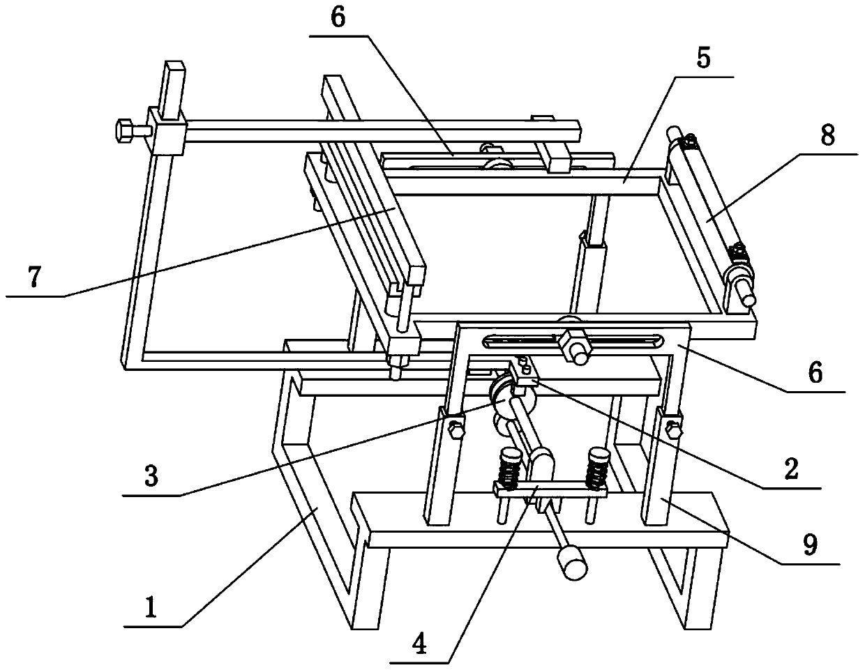
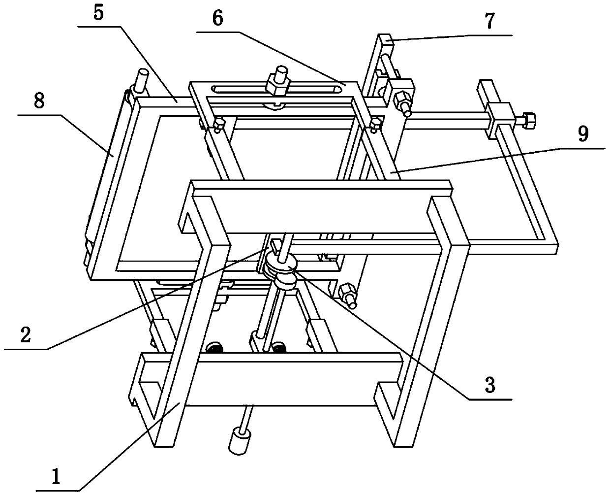
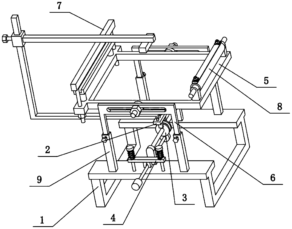
[0045] Combine below Figure 1-14 This embodiment is described. The present invention relates to the field of fabric light transmission detection, more specifically, a fabric light transmission detection system and detection method, including a base 1, a light emitter 2, a light receiver 24, an adjuster 3, and a fixing frame 5 and the fixed frame support 6 are detection systems in the present invention that can carry out light transmission detection to fabrics in various situations.

[0046] The light emitter 2 is arranged on the top of the base 1, the light emitter 2 can move back and forth, and the light emitter 2 can rotate on a vertical plane, the position of the light emitter 2 is adjusted by the regulator 3, and the light receiver 24 Corresponding to the light emitter 2, the light receiver 24 is always arranged in the direction of the light emitted by the light emitter 2, the front and rear ends of the base 1 are fixedly connected with the fixed frame bracket 6, and the ...

specific Embodiment approach 2

[0048] Combine below Figure 1-14 To illustrate this embodiment, the regulator 3 includes a rotating cylinder 31 and a fixed shaft 32, the fixed shaft 32 is fixedly connected to the upper end of the base 1, the center of the rotating cylinder 31 is slidably connected to the fixed shaft 32, and the rotating cylinder 31 is threaded. A fastening screw 1 is connected, and the fastening screw 1 abuts on the fixed shaft 32 to fix the rotating cylinder 31, and the light emitter 2 is fixedly connected to the rotating cylinder 31. The rotating cylinder 31 can slide back and forth on the fixed shaft 32, and the rotating cylinder 31 can rotate on the fixed shaft 32 with the axis of the fixed shaft 32 as the axis, so that the light emitter 2 can move back and forth, and the light emitter 2 can be moved vertically. Rotate on a straight plane. Rotating fastening screw 1 is abutted on fixed shaft 32 and can be fixed at any time by rotating cylinder 31.

specific Embodiment approach 3

[0050] Combine below Figure 1-14 To illustrate this embodiment, the adjuster 3 includes a rotating cylinder 31, a fixed shaft 32, a convex seat 33, a ring groove 34, a gear 35 and a sliding shaft 36, the front and rear ends of the base 1 are fixedly connected with the convex seat 33, two A fixed shaft 32 is fixedly connected between the protrusions 33, and the center position of the rotating cylinder 31 is slidably connected to the fixed shaft 32. An annular groove 34 is arranged on the outer ring of the rotating cylinder 31, and the inner ring of the annular groove 34 is uniformly distributed in the radial direction. A plurality of gear teeth, the sliding shaft 36 is slidably connected to one of the convex seats 33, and one end of the sliding shaft 36 is fixedly connected to a gear 35, the gear 35 is inserted in the ring groove 34, and the gear 35 and the plurality of gears on the inner ring of the ring groove 34 Gear meshing transmission, the slide shaft 36 is fixed by the ...


PUM


Abstract

The invention relates to the field of fabric light transmission detection, more particularly to a fabric light transmission detection system and a detection method thereof. The detection system comprises a base, a light emitter, a light receiver, a regulator, a fixed frame and fixed frame brackets. The detection system is capable of carrying out light transmission detection on the fabric under various conditions. The light emitter disposed above the base can move back and forth and can rotate on a vertical plane, wherein the position of the light emitter is adjusted by the regulator. The lightreceiver corresponds to the light emitter; and the light receiver is always disposed in the direction of the light emitted by the light emitter. The frontend and the rear end of the base are fixedlyconnected with the fixed frame brackets; and the fabric fixed frame is arranged between the two fixed frame brackets. The light receiver and the light emitter are respectively arranged at the upper side and the lower side of the fabric fixed frame.

Description

technical field [0001] The invention relates to the field of fabric light transmission detection, in particular to a fabric light transmission detection system and detection method. Background technique [0002] The application number is CN201721077766.5, which discloses a silk screen light transmission detection equipment applied to photovoltaic glass. The utility model discloses a silk screen light transmission detection equipment applied to photovoltaic glass. The detection equipment includes a workbench. A raised cavity is uniformly arranged on the workbench, and the interior of the raised cavity is used to place a point light source based on the silk screen area of ​​the photovoltaic glass. When performing light transmission detection operations, the photovoltaic glass can be placed on the On the plane formed by the top surface of the raised cavity, the light-transmitting detection device also includes a light-tight cover plate, and the outline size of the light-proof c...

Claims


Application Information

Patent Timeline
IPC IPC(8): G01N21/59
CPCG01N21/59
Inventor 潘一洲
Owner 东莞市听雨轩服装有限公司
Why Eureka
Try Eureka