A kind of fabric light transmission detection system and detection method
A detection system and fabric technology, applied in the direction of transmittance measurement, etc., can solve the problems of fabric light transmission detection and other problems
- Summary
- Abstract
- Description
- Claims
- Application Information
AI Technical Summary
Problems solved by technology
Method used
Image
Examples
specific Embodiment approach 1
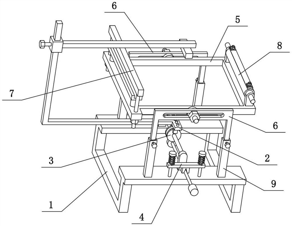
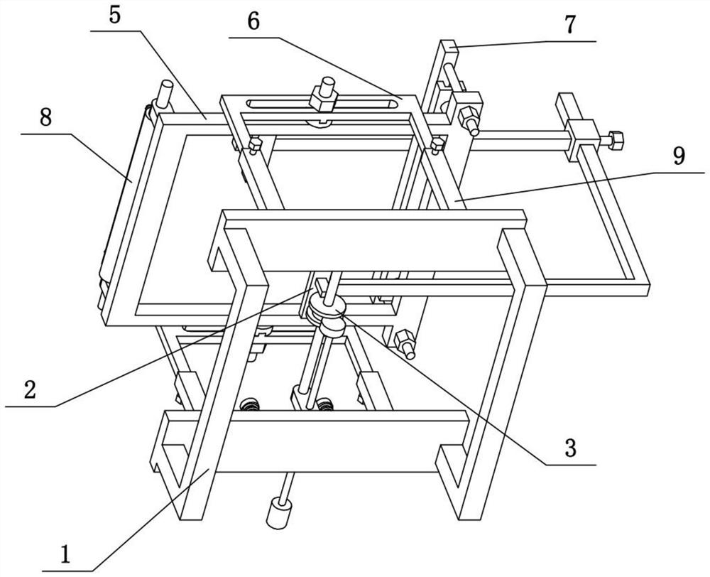
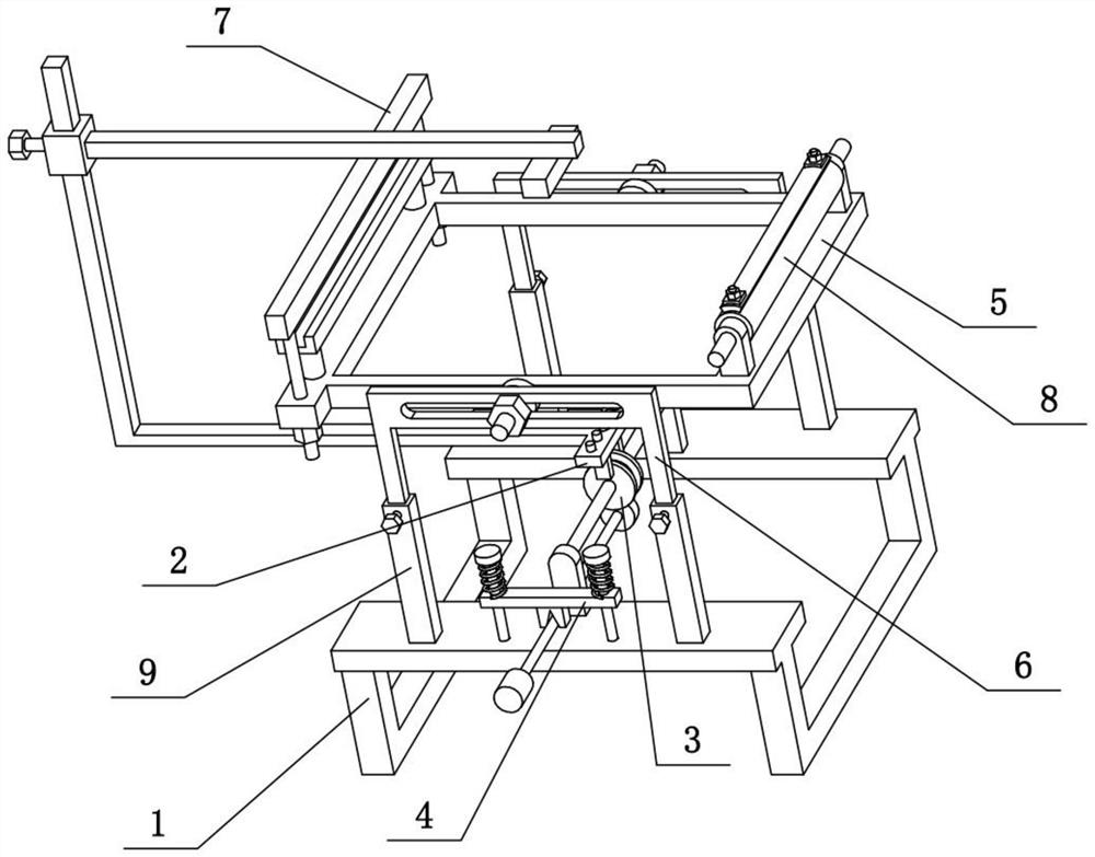
[0045] Combine below Figure 1-14 This embodiment is described. The present invention relates to the field of fabric light transmission detection, more specifically, a fabric light transmission detection system and detection method, including a base 1, a light emitter 2, a light receiver 24, an adjuster 3, and a fixing frame 5 and the fixed frame support 6 are detection systems in the present invention that can carry out light transmission detection to fabrics in various situations.
[0046] The light emitter 2 is arranged on the top of the base 1, the light emitter 2 can move back and forth, and the light emitter 2 can rotate on a vertical plane, the position of the light emitter 2 is adjusted by the regulator 3, and the light receiver 24 Corresponding to the light emitter 2, the light receiver 24 is always arranged in the direction of the light emitted by the light emitter 2, the front and rear ends of the base 1 are fixedly connected with the fixed frame bracket 6, and the ...
specific Embodiment approach 2
[0048] Combine below Figure 1-14 To illustrate this embodiment, the regulator 3 includes a rotating cylinder 31 and a fixed shaft 32, the fixed shaft 32 is fixedly connected to the upper end of the base 1, the center of the rotating cylinder 31 is slidably connected to the fixed shaft 32, and the rotating cylinder 31 is threaded. A fastening screw 1 is connected, and the fastening screw 1 abuts on the fixed shaft 32 to fix the rotating cylinder 31, and the light emitter 2 is fixedly connected to the rotating cylinder 31. The rotating cylinder 31 can slide back and forth on the fixed shaft 32, and the rotating cylinder 31 can rotate on the fixed shaft 32 with the axis of the fixed shaft 32 as the axis, so that the light emitter 2 can move back and forth, and the light emitter 2 can be moved vertically. Rotate on a straight plane. Rotating fastening screw 1 is abutted on fixed shaft 32 and can be fixed at any time by rotating cylinder 31.
specific Embodiment approach 3
[0050] Combine below Figure 1-14 To illustrate this embodiment, the adjuster 3 includes a rotating cylinder 31, a fixed shaft 32, a convex seat 33, a ring groove 34, a gear 35 and a sliding shaft 36, the front and rear ends of the base 1 are fixedly connected with the convex seat 33, two A fixed shaft 32 is fixedly connected between the protrusions 33, and the center position of the rotating cylinder 31 is slidably connected to the fixed shaft 32. An annular groove 34 is arranged on the outer ring of the rotating cylinder 31, and the inner ring of the annular groove 34 is uniformly distributed in the radial direction. A plurality of gear teeth, the sliding shaft 36 is slidably connected to one of the convex seats 33, and one end of the sliding shaft 36 is fixedly connected to a gear 35, the gear 35 is inserted in the ring groove 34, and the gear 35 and the plurality of gears on the inner ring of the ring groove 34 Gear meshing transmission, the slide shaft 36 is fixed by the ...
PUM
 Abstract
Description
Claims
Application Information
 - R&D
- Intellectual Property
- Life Sciences
- Materials
- Tech Scout
- Unparalleled Data Quality
- Higher Quality Content
- 60% Fewer Hallucinations
Browse by: Latest US Patents, China's latest patents, Technical Efficacy Thesaurus, Application Domain, Technology Topic, Popular Technical Reports.
© 2025 PatSnap. All rights reserved.Legal|Privacy policy|Modern Slavery Act Transparency Statement|Sitemap|About US| Contact US: help@patsnap.com


