Collision detecting device and method

a detection device and detection method technology, applied in x-ray apparatus, radiation therapy, gamma-ray/particle irradiation therapy, etc., can solve the problem that the operator may interrupt the displacement of the patien

Active Publication Date: 2009-02-17
ELEKTA AB
View PDF3 Cites 0 Cited by
  • Summary
  • Abstract
  • Description
  • Claims
  • Application Information

AI Technical Summary

Benefits of technology

[0009]It is an object of the present invention to eliminate the drawbacks and disadvantages of the prior art and provide a collision detecting device capable of detecting any collision between a radiation treatment unit and a patient / body part or any equipment attached thereto, which is reliable as well as simple to manufacture, install and use and hence inexpensive. At least this object is achieved by a collision detecting device according to the present invention.
[0013]The collision detecting unit may be manufactured in different ways and of various materials. In one embodiment the collision detecting unit is made of an electrically insulating material, e.g. plastics which preferably can be extruded or injection moulded into the desired shape. Subsequently the collision detecting unit is provided with an electrically conducting layer on the outside, e.g. an electrically conducting paint or a metal foil. In this way the inside of the collision detecting unit will be electrically insulated, which will protect the patient from electrical shocks in case of a collision.
[0017]The form and material of the spacer elements is optional. The main requirement is that they should be able to hold the collision detecting unit securely in an electrically insulating way on a small distance from the interior surfaces of the radiation unit. In one embodiment the spacer elements are strips of tape fastened to the outside of the collision detecting unit. Such spacer elements are inexpensive as well as easily and quickly fastened wherever it is suitable, and are able to hold the collision detecting unit at a very short distance from the interior surface of the radiation unit. However, it is possible to manufacture the spacer elements of other materials and with different shapes, such as elastic spacer elements as mentioned hereinbefore. It also would be possible to form the spacer elements simultaneously as injection moulding of the plastic body to the collision detecting unit, and consequently of the same material as and integral with the plastic body.
[0019]In a preferred embodiment, the collision detecting unit is connected to the voltage supply as well as the gauge indicator or the monitoring device, through one or more spring-loaded touch probes, which abuts against the electrically conducting layer on the outside of the collision detecting unit and transmits voltage to and / or from the same. A detachable touch probe of this kind makes the collision detecting unit easy to install and detach. However, it should be understood that the electrical connection also could be e.g. a fixed connection which consists of for example a wire soldered to the collision detecting unit.
[0020]In one embodiment, the collision detecting device according to the invention, is provided with only one touch probe, i.e. one single probe connects the collision detecting unit to the voltage supply as well as to the gauge indicator or the monitoring equipment. In another embodiment there are provided two separate touch probes, one for transmitting voltage to the collision detecting unit, and another for monitoring voltage level in the collision detecting unit. In this way the probability that a collision could occur, without it being detected, in consequence of a single touch probe being out of contact, is eliminated. With two separate touch probes, the gauge indicator or monitoring equipment is detecting collision if one of the touch probes is out of contact, which gives the operating personnel an opportunity to check the equipment before operation.
[0021]In an alternative embodiment, the collision detecting unit can be provided with electrically separated sectors in the outside conductive layer, each connected by one or two separate connecting means as described above. With such an arrangement it is possible to get an indication in what sector of the radiation unit a possible collision has occurred and to control an automatic displacement device to avoid the collision.

Problems solved by technology

The operator may then interrupt the displacement of the patient if a collision is detected.

Method used


Image

  • Collision detecting device and method
  • Collision detecting device and method
  • Collision detecting device and method

Examples


Embodiment Construction

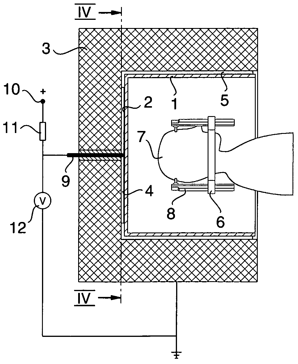
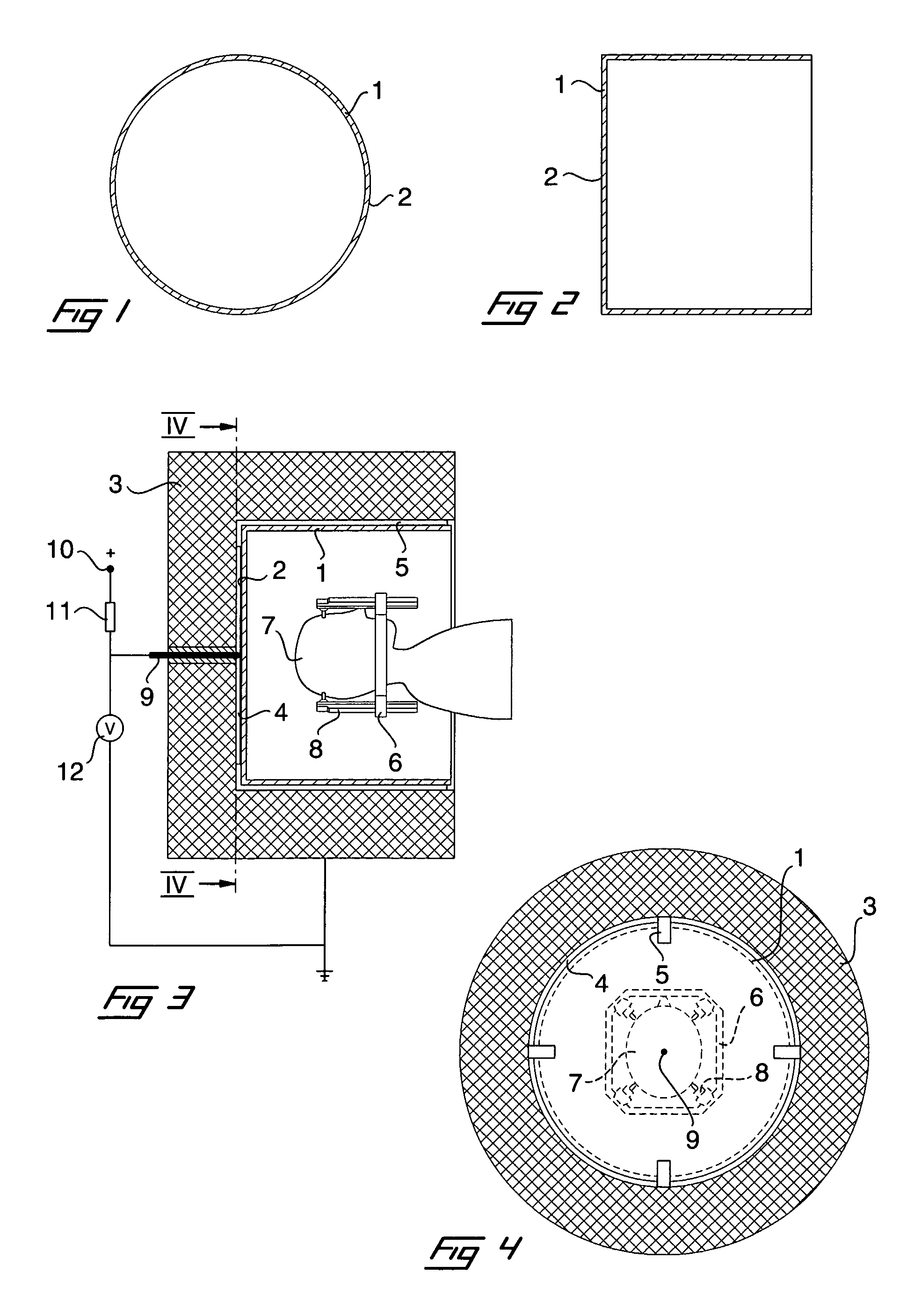
[0029]In FIGS. 1 and 2 is shown an embodiment of a collision detecting unit 1 according to the invention. The shape of the collision detecting unit is determined by the shape of an internal space of a radiation unit to be inserted in. For the sake of simplicity the collision detecting unit is depicted as a simple cylindrical bowl, having a circular cross-section and one end closed. However, in practice the collision detecting unit may have a more intricate shape.

[0030]The collision detecting unit is preferably made of plastics, e.g. by injection moulding or any other suitable manufacturing method, and has thin, flexible walls which may easily deflect when subjected to a force.

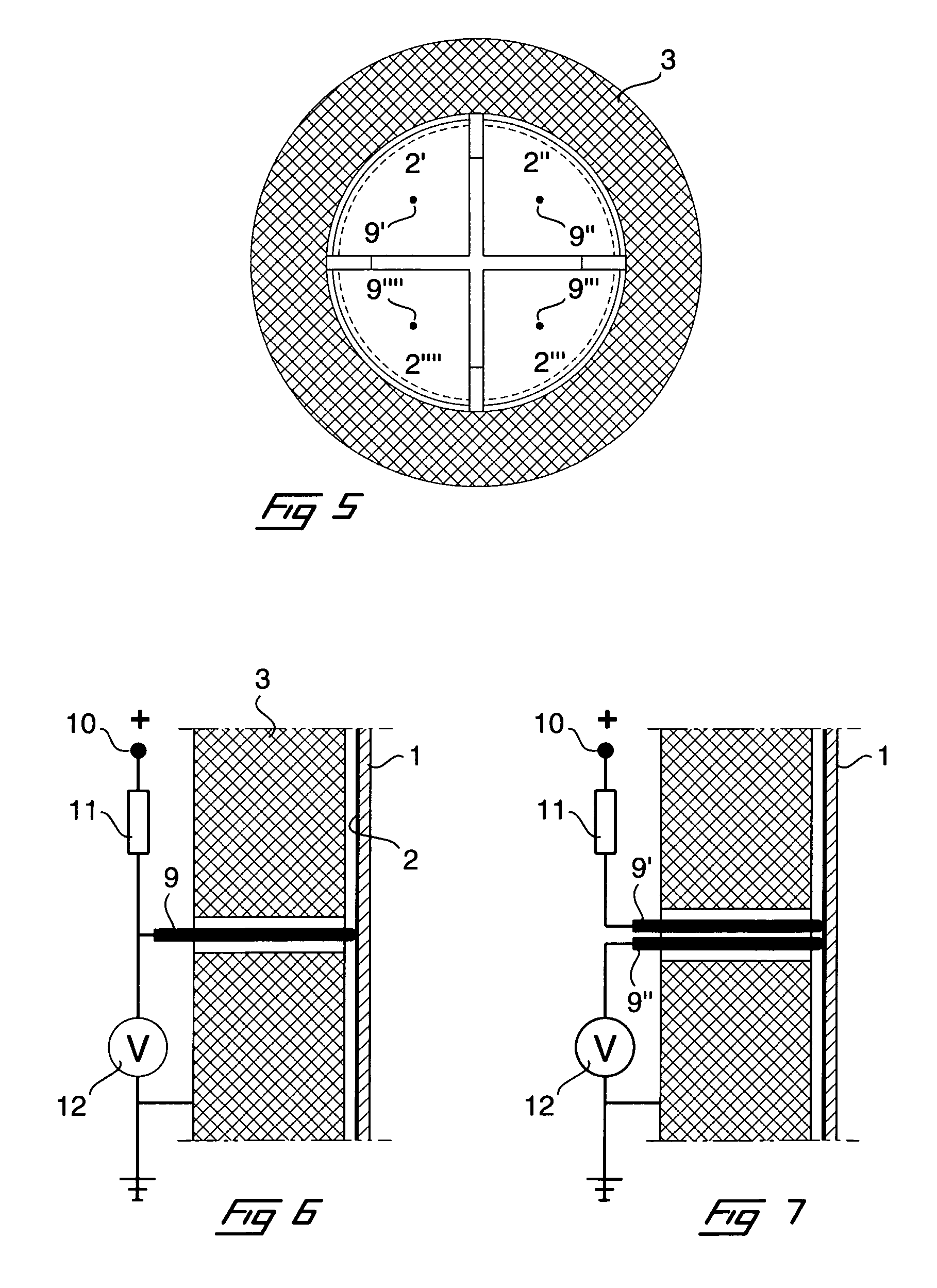
[0031]Accordingly, the body of the collision detecting unit is electrically insulating. In accordance with the invention, however, the outer surfaces of the collision detecting unit, is provided with an electrically conductive layer 2, preferably of an electrically conductive paint, but other types of layers ma...


PUM


Abstract

The present invention relates to a collision detecting device for a radiation treatment apparatus, comprising a radiation unit having an internal space, for directing radiation beams towards a radiological focus in the internal space for treatment of a target in a patient's body therein. The collision detecting device comprises a collision detecting unit being electrically conductive at least on its outer surface and having a size slightly smaller than the internal space of the radiation unit, so as to be insertable into the internal space and held in an electrically insulating manner in respect of the radiation unit by spacer elements. The outer electrically conductive surface is connectible to an electrical voltage supply in order to detect if the outer surface of the collision detecting unit abuts against the inside surface of the radiation unit. The invention also relates to a method for performing such collision detection.

Description

[0001]This is a 35 U.S.C. §371 filing of International Patent Application No. PCT / SE2005 / 000991, filed Jun. 23, 2005, which claims the benefit under 35 U.S.C. §119 (a)-(d) of Swedish Application No. 0401695-2, filed Jul. 1, 2004, and under 35 U.S.C.§119 (e) of U.S. Provisional Patent Application No. 60 / 583,361, filed Jun. 29, 2004.TECHNICAL FIELD[0002]The present invention relates to a collision detecting device for a radiation treatment apparatus, comprising a radiation unit having an internal space, for directing radiation beams towards a radiological focus in the internal space for treatment of a target in a patient's body therein. More precisely the collision detecting device functions to detect whether the body part or any equipment connected thereto, comes in contact with surfaces defining the internal space of the radiation unit when moving the patient inside the space to position the target to be treated in the radiological focus.[0003]The invention also relates to a method ...

Claims


Application Information

Patent Timeline
Patent Type & Authority Patents(United States)
IPC IPC(8): H05G1/54A61NA61N5/10
CPCA61N5/1084
Inventor NIVESTEDT, HAKANMINOZ, ALAIN
Owner ELEKTA AB
Why Eureka
Try Eureka