

Display device
a display device and display technology, applied in the field of display devices, can solve problems such as accidental application of force, and achieve the effect of high portability
- Summary
- Abstract
- Description
- Claims
- Application Information
AI Technical Summary
Benefits of technology
Problems solved by technology
Method used
Image

Examples
embodiment 1
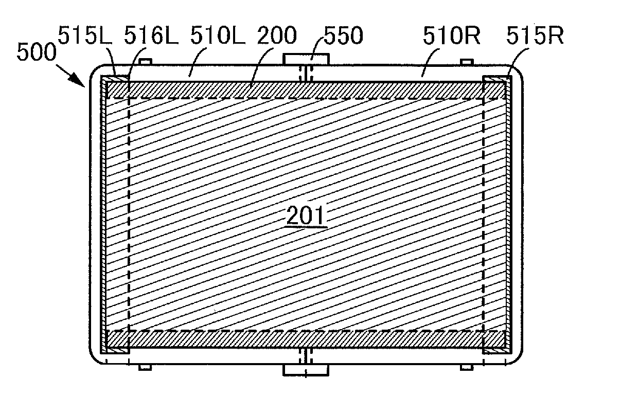
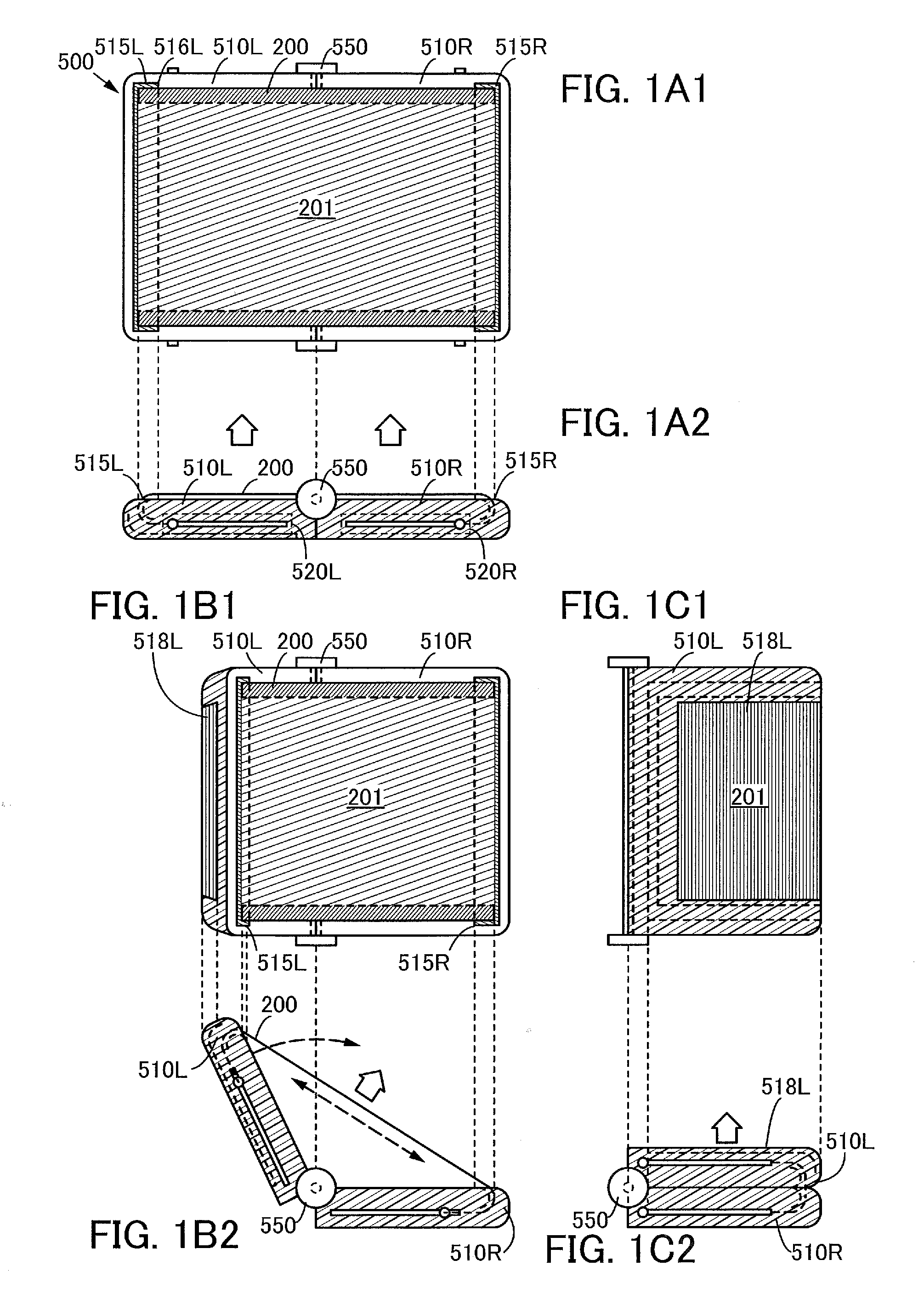
[0036]In this embodiment, a structure of a display device of one embodiment of the present invention will be described with reference to FIGS. 1A1, 1A2, 1B1, 1B2, 1C1, and 1C2 and FIGS. 2A and 2B.
[0037]FIGS. 1A1, 1B1, and 1C1 are plan views of the display device of one embodiment of the present invention. FIGS. 1A2, 1B2, and 1C2 are side views corresponding to FIGS. 1A1, 1B1, and 1C1, respectively.
[0038]FIGS. 1A1 and 1A2 illustrate a state in which the display device of one embodiment of the present invention is developed.
[0039]FIGS. 1B1 and 1B2 illustrate a state in which the display device of one embodiment of the present invention is folded halfway.
[0040]FIGS. 1C1 and 1C2 illustrate a state in which the display device of one embodiment of the present invention is folded up.
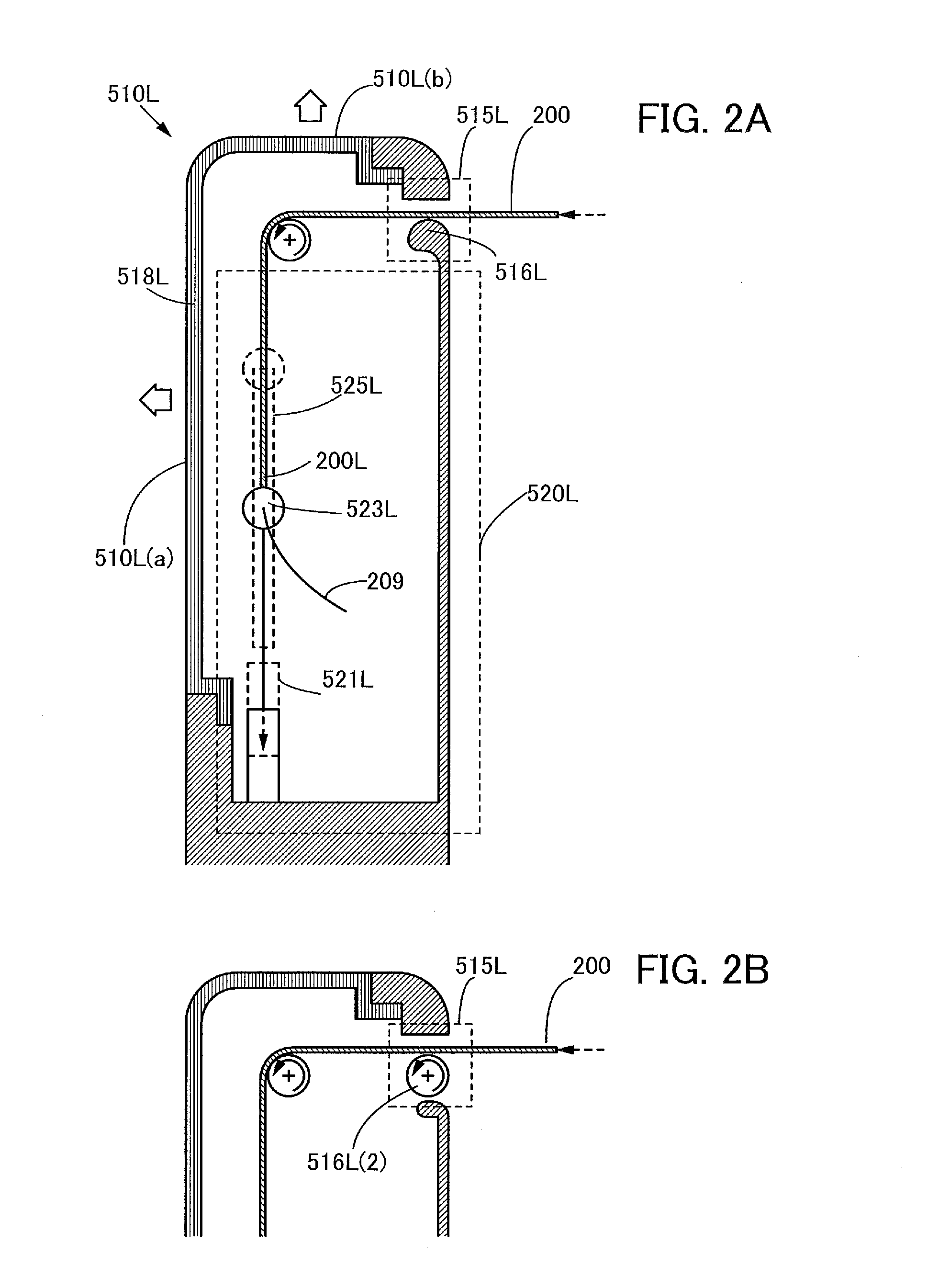
[0041]FIGS. 2A and 2B schematically illustrate structures of a storage portion that can be employed in the display device of one embodiment of the present invention.
[0042]A display device 500 described in this ...
embodiment 2
[0080]In this embodiment, a structure of a display panel that can be used in the display device of one embodiment of the present invention will be described with reference to FIGS. 3A to 3C.
[0081]FIG. 3A is a plan view illustrating the structure of a display panel that can be used in the display device of one embodiment of the present invention.
[0082]FIG. 3B is a cross-sectional view taken along line A-B and line C-D in FIG. 3A.
[0083]FIG. 3C is a cross-sectional view taken along line E-F in FIG. 3A.
[0084]The display panel 200 described as an example in this embodiment includes one end 200L and the other end 200R (see FIG. 3A).
[0085]Furthermore, the display panel 200 described as an example in this embodiment includes the display region 201.
[0086]In the display region 201, a plurality of pixels 202 is provided, and a plurality of sub-pixels (e.g., a sub-pixel 202R) is provided in each of the pixels 202. In addition, in the sub-pixels, light-emitting elements and pixel circuits that c...
embodiment 3
[0109]In this embodiment, a structure of a display portion that can be used in the display device of one embodiment of the present invention and a structure of a foldable touch panel that can be used in a positional information input portion will be described with reference to FIGS. 4A to 4C.
[0110]FIGS. 4A to 4C illustrate the structure of a touch panel that can be used in a data processing device in one embodiment of the present invention.
[0111]FIG. 4A is a plan view and FIG. 4B is a cross-sectional view taken along line A-B and line C-D in FIG. 4A.
[0112]FIG. 4C is a cross-sectional view taken along line E-F in FIG. 4A.
[0113]A touch panel 300 described as an example in this embodiment includes a display portion 301 (see FIG. 4A).
[0114]The display portion 301 includes a plurality of pixels 302 and a plurality of imaging pixels 308. The imaging pixels 308 can sense a touch of a finger or the like on the display portion 301. Thus, a touch sensor can be formed using the imaging pixels ...
PUM
 Abstract
Description
Claims
Application Information