Supercharge Your Innovation With Domain-Expert AI Agents!

Pump System

a pump system and pump technology, applied in the direction of machines/engines, liquid fuel engines, positive displacement liquid engines, etc., can solve the problems of reduced performance, loss of service life, and difficulty in economically producing hydrocarbons from low-permeability reservoir rocks

Inactive Publication Date: 2014-10-30
FORUM US
View PDF11 Cites 72 Cited by
  • Summary
  • Abstract
  • Description
  • Claims
  • Application Information

AI Technical Summary

Benefits of technology

The patent text discusses the challenges faced by pump systems used in hydraulic fracturing, which involves delivering fracture fluids under high pressure to create channels for oil and gas to flow through. The technical problem addressed in the patent text is the need for improved pump systems that can better withstand the harsh environments and operating conditions of oil field well service applications, including pumping fracture fluids. The patent text discusses various issues such as pump cavitation, cracking and failure, improper maintenance, and improper operation that can reduce performance and lifespan of pumps. The patent text also highlights the need for an improved discharge valve without wings to prevent excessive wear and leaks around valve seats. Additionally, the patent text discusses the challenge of replacing the sealing elements in suction and discharge valves without disassembling the pump, which is time-consuming and difficult to perform in the field. The patent text also mentions the need for multi-piece connecting rods to minimize rod replacement time by permitting just the worn portions to be swapped, but the current design of these rods is not widely accepted due to wear that occurs not only in the usual spots, but also at the junctions between the joined pieces. The patent text also discusses the importance of proper design of bearings that couple connecting rods to a crankshaft within the power end to prevent friction and damage to the pump.

Problems solved by technology

It is difficult to economically produce hydrocarbons from low permeability reservoir rocks.
The four main issues that contribute to reduced performance and the loss of service life in these pumps are: 1) Pump cavitation due to inadequate and or inconsistent charge flow; 2) Cracking and Failure due to metal fatigue in the pump fluid ends which are also known as the liquid or pressure sides of the pump.
This is caused by the continual high pressurization & de-pressurization that occurs up to three times per second as the pump reciprocates to displace liquid under pressure; 3) Improper maintenance; and 4) Improper operation.
A valve that has too many internal projections can capture or “knock out” enough proppant to block the flow of fluid through a pump, requiring that time and effort be invested to clear the blockage—a costly undertaking.
Also, these projections can create substantial pressure losses that require more energy to be expended than is necessary to perform hydraulic fracturing work.
Typical designs of sealing elements have permitted them to move about in their retaining grooves after installation, permitting them to wear excessively in the presence of abrasive proppants and other materials carried by fracture fluids.
Thus, the known sealing elements required frequent replacement.
To access the worn sealing elements, the fluid end frequently required substantial disassembly.
Although manufacturers provide strong and robust pumps, disassembly of pumps in the field is especially time-consuming and difficult to perform.
The plungers also rub against sealing elements in the ends of the pumping chambers and, consequently, are worn and abraded by proppants and other materials carried in the pumped fluids.
When portions of such a connecting rod wear out, the rod must be replaced in its entirety—a time-consuming and costly project.
Multi-piece rods have not, however, gained widespread acceptance since wear tends to occur not only in the usual spots, but, also, at the junctions between the joined pieces.
Improper design of these sleeves, however, can restrict the flow of lubricant to the surfaces contacting the crankshaft.
If flow is impeded, the sleeves and the pump can be damaged.
Damage can be caused by the sleeves seizing upon the crankshaft so that they grind against their housings and by galling where they wear against the crankshaft.
Such an event can be time consuming and costly for an oilfield operator conducting a frac job.
It is the connections between the parts and the supporting features within the pump system that tend to weaken the pump system, limiting its pressure rating, and making it susceptible to corrosion, leaks, and cracks under high, cyclical stresses.
Thus, pump systems sometimes fail under load prematurely.
In an effort to increase pressure ratings and decrease failure rates, improved fluid ends have been proposed by pump manufacturers, however the designs have not seen widespread use or commercial success since they have been difficult and costly to make and equally difficult to service in the field.

Method used


Image

  • Pump System
  • Pump System
  • Pump System

Examples


first embodiment

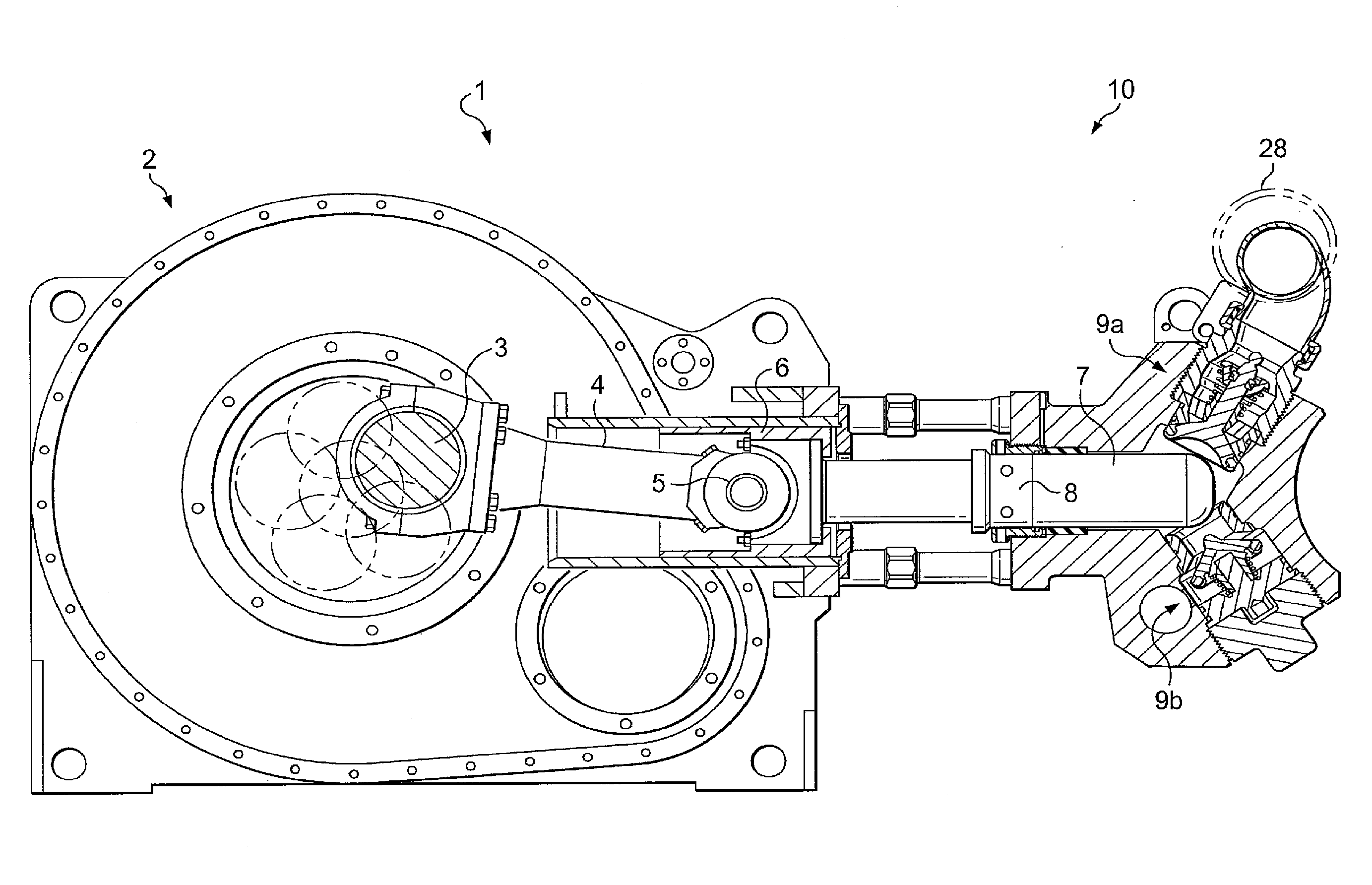
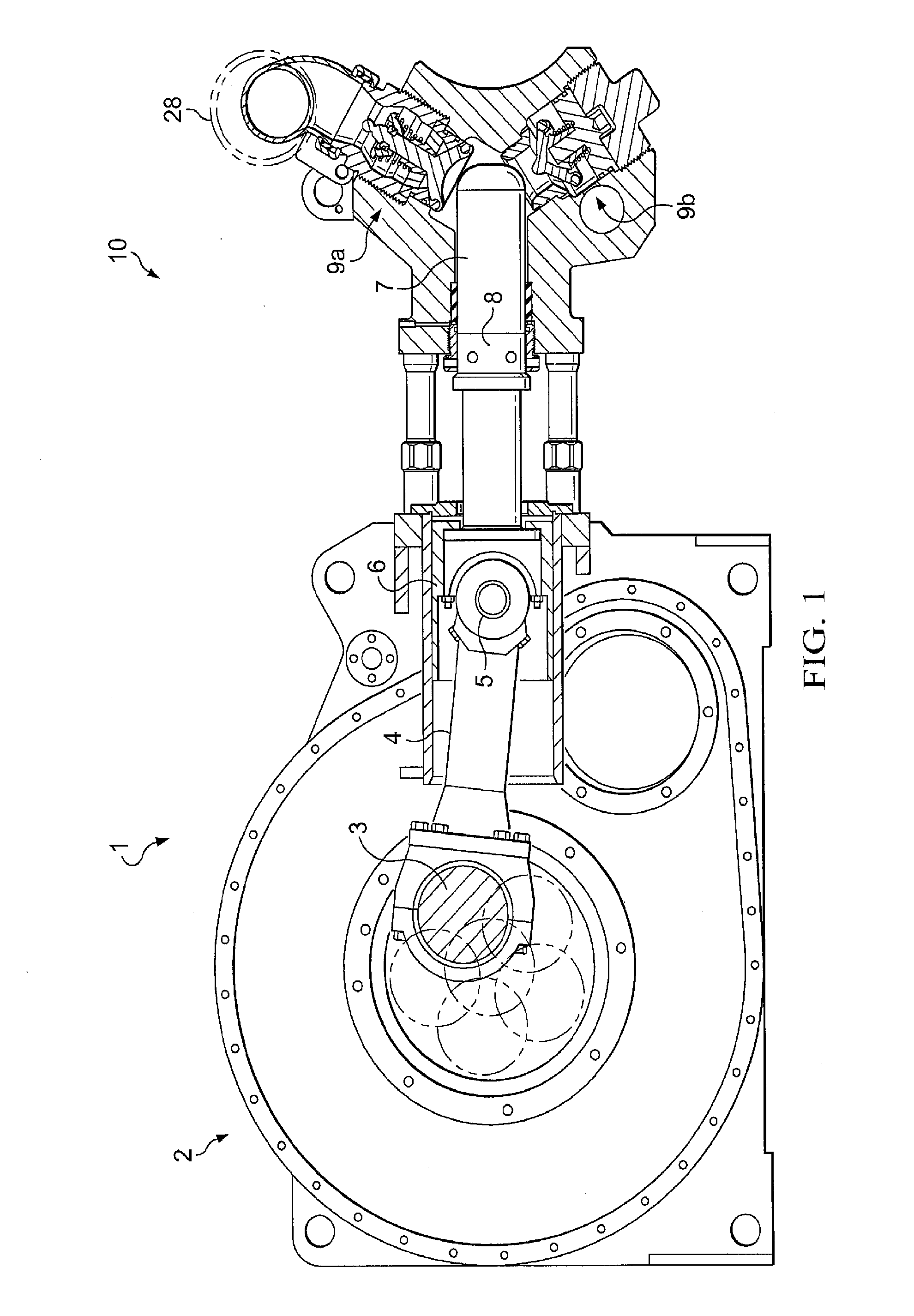
[0126]Referring now to FIGS. 11-14 in the drawings, a fluid end assembly 10 is illustrated according to the present application. Fluid assembly 10 shows a Y-shaped intersection between plunger 16, suction valve 24, and discharge valve 26. Fluid end 10 is configured to reduce metal fatigue in the fluid end and increase ease of maintenance. In particular to FIGS. 11 and 12 of the drawings, fluid end assembly 10 includes a pump housing 12 having a plunger bore 14 within which a plunger 16 reciprocates. At its inner end, plunger bore 14 terminates in a pumping chamber 18 that is supplied with fluid from above by a suction passage 20 in pump housing 12. Fluid pressurized by plunger 16 exits pumping chamber 18 downwardly through a discharge passage 22 in pump housing 12. A suction valve 24 in suction passage 20 establishes the one-way flow of fluid from a supply manifold 28 into pumping chamber 18. A discharge valve 26 in discharge passage 22 sets up the one-way flow of fluid from pumping...

second embodiment

[0144]Referring now to FIGS. 13 and 14 of the drawings, a fluid end assembly is shown at 410. Fluid end assembly 410 is substantially the same as fluid end assembly except that a suction valve 424 and a discharge valve 426, and the passages 420 and 422 for the valves 424 and 426, have been modified somewhat. These modifications are believed to further strengthen valves 424 and 424 and fluid end assembly 410.

[0145]Fluid end assembly 410 includes a pump housing 412 having a plunger bore 414 within which a plunger 416 reciprocates. At its inner end, plunger bore 414 terminates in a pumping chamber 418 that is supplied with fluid by a suction passage 420 in pump housing 412. Fluid pressurized by plunger 416 exits pumping chamber 418 through a discharge passage 422 in pump housing 412 located opposite suction passage 420. A suction valve 424 in suction passage 420 permits the one-way flow of fluid from a supply manifold 428 to pumping chamber 418. A discharge valve 426 in discharge passa...


PUM


Abstract

A pump system that has a power end and a fluid end assembly. The fluid end assembly includes a plunger configured to translate within a plunger bore. The fluid end further includes a suction valve assembly and a discharge valve assembly. The power end is configured to use a pony rod to induce movement of the plunger within the fluid end assembly to generate a pressure differential. The suction valve assembly and the discharge assembly operate in response to the pressure differential to move the fluid. A straight valve seal is located within the suction valve assembly and / or the discharge valve assembly to distribute forces incurred by movement of valves within the fluid end assembly.

Description

TECHNICAL FIELD[0001]The application relates generally to pump systems having a power end in operative communication with a fluid end and, more particularly, to a pump system for delivering fracture fluids.DESCRIPTION OF THE PRIOR ART[0002]It is difficult to economically produce hydrocarbons from low permeability reservoir rocks. Oil and gas production rates are often boosted by hydraulic fracturing, a technique that increases rock permeability by opening channels through which hydrocarbons can flow to recovery wells. During hydraulic fracturing, a fluid is pumped into the earth under high pressure (sometimes as high as 50,000 PSI) where it enters a reservoir rock and cracks or fractures it. Large quantities of proppants are carried in suspension by the fluid into the fractures. When the pressure is released, the fractures partially close on the proppants, leaving channels for oil and gas to flow.[0003]Specialized pump systems are used to deliver fracture fluids at sufficiently high...

Claims


Application Information

Patent Timeline
IPC IPC(8): F04B49/22
CPCF04B49/22F04B47/02F04B53/10F04B53/102F04B53/1087F04B53/144
Inventor MARETTE, MICHAEL DAVIDDOMINGUEZ, SAUL
Owner FORUM US
Features
  • R&D
  • Intellectual Property
  • Life Sciences
  • Materials
  • Tech Scout
  • Unparalleled Data Quality
  • Higher Quality Content
  • 60% Fewer Hallucinations
Learn More