Screwdriver for bone screws

a screwdriver and bone screw technology, applied in the field of screwdrivers, can solve the problems of multiple screwdrivers, difficult handling of different bone screws, etc., and achieve the effects of simple operation of screwdrivers, easy screwing out, and high functional reliability of adjustment devices

Inactive Publication Date: 2014-10-30
SILONY MEDICAL INT
View PDF4 Cites 40 Cited by
  • Summary
  • Abstract
  • Description
  • Claims
  • Application Information

AI Technical Summary

Benefits of technology

[0017]According to a further advantageous embodiment of the screwdriver according to the invention, the adjustment device is a spring-loaded pushbutton which acts perpendicularly to the longitudinal direction of the screwdriver, which pushbutton has a recess which receives a shaft and a cutaway in the recess which cooperates with the cross-sectional tapers in such a manner that actuation of the pushbutton enables an adjustment of the shaft relative to the sleeve and an adjustment is prevented when the pushbutton is not actuated. With this the adjustment device is very compact. The spring-loaded pushbutton with the central recess for receiving the shaft also ensures a high functional reliability of the adjustment device.
[0018]According to a further advantageous embodiment of the invention, the distal sleeve has at its proximal end a thread which serves for fastening in a counter thread on the bone screw. At their fork head the bone screws usually have an inner thread, which serves for subsequent screwing in of a grub screw for fastening for example a vertebral rod. Into this thread the sleeve for holding the fork head can be screwed and after fastening the bone screw can be easily screwed out again.
[0019]According to a further advantageous embodiment of the screwdriver according to the invention, the handle is configured as a hand grip which extends transverse to the longitudinal direction of the shaft and is essentially a T-shaped hand grip on the proximal end of the screwdriver. This enables a simple operation of the screwdriver and a sufficient pressure can easily be generated by the user. In addition this also ensures that a user is able to securely hold the screwdriver with both hands.
[0020]According to a further advantageous embodiment of the invention, the turn handle is configured as a hollow tool handle, which extends in longitudinal direction of the shaft. In the interior of the hollow space of the turn handle the adjustment device according to the invention can thus easily be integrated. This also simplifies the handling of the screwdriver, because during screwing the bone screws in or out the user can securely hold the screwdriver on the turn handle with one hand and with the other hand on the front handle.
[0021]According to a further advantageous embodiment of the invention, a guiding wire is provided in the interior of the through opening of the shaft, which guiding wire serves for defining and for locating the correct position of the desired site of the bone screw in the bone. The guiding wire can completely be guided through the interior of the shaft without interfering with the function of the screwdriver and after placing the bone screw can be easily removed again. Such a guiding wire is usually fastened to the bone beforehand so that the bone screw, which is threaded thereon can be screwed in at the right site at the bone.
[0022]According to a further advantageous embodiment of the invention, the formfitting or force-fitting profile of the screwdriver and / or the connecting means is / are configured replaceable on the distal sleeve. The versatility of the screwdriver is thus increased. Different shapes, sizes or types of bone screws can be actuated with the same screwdriver by exchanging the corresponding parts

Problems solved by technology

This has the disadvantage that on one hand multiple different screwdrivers have to be provided for the different types, versions and lengths of bone screws.
On the other hand the handling of these different bone screws is made difficult because the user has to correctly associate the fitting screwdriver to the corresponding types of bone screws for example by a corresponding marking or coding.

Method used


Image

  • Screwdriver for bone screws
  • Screwdriver for bone screws
  • Screwdriver for bone screws

Examples


Embodiment Construction

[0032]Throughout all the Figures, same or corresponding elements are generally indicated by same reference numerals. These depicted embodiments are to be understood as illustrative of the invention and not as limiting in any way. It should also be understood that the drawings are not necessarily to scale and that the embodiments are sometimes illustrated by graphic symbols, phantom lines, diagrammatic representations and fragmentary views. In certain instances, details which are not necessary for an understanding of the present invention or which render other details difficult to perceive may have been omitted.

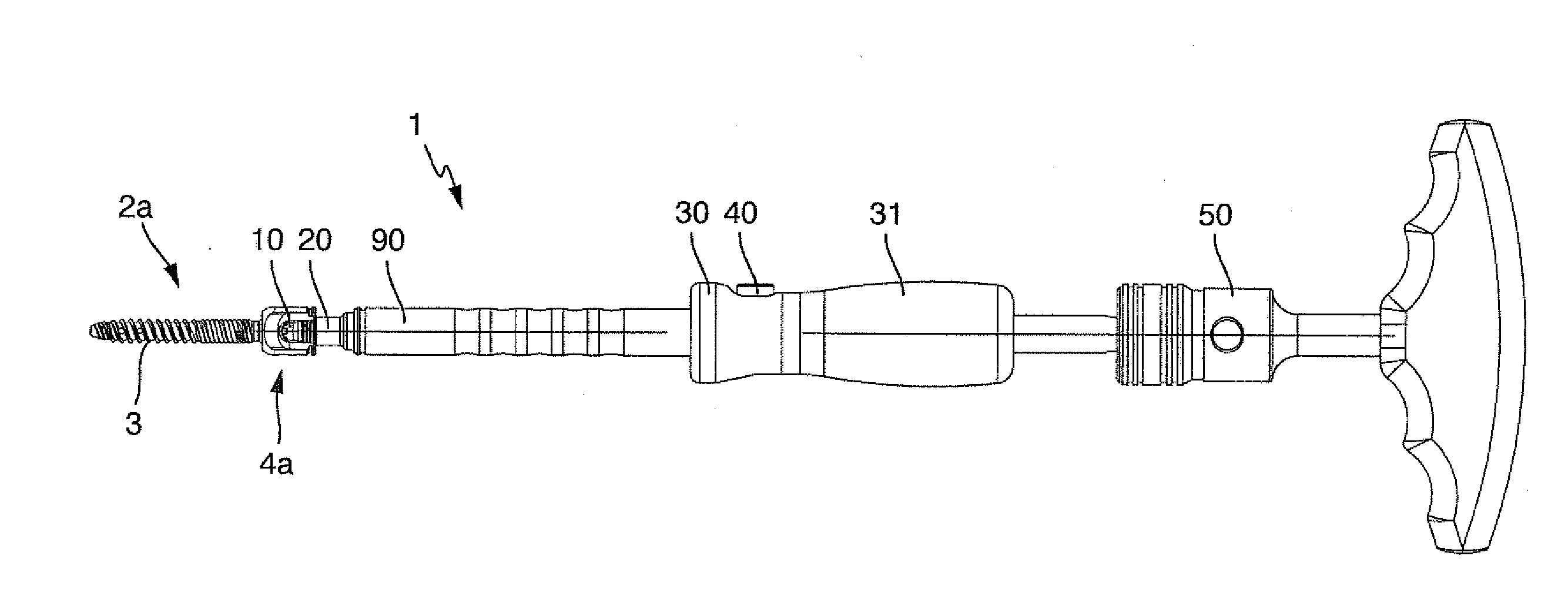
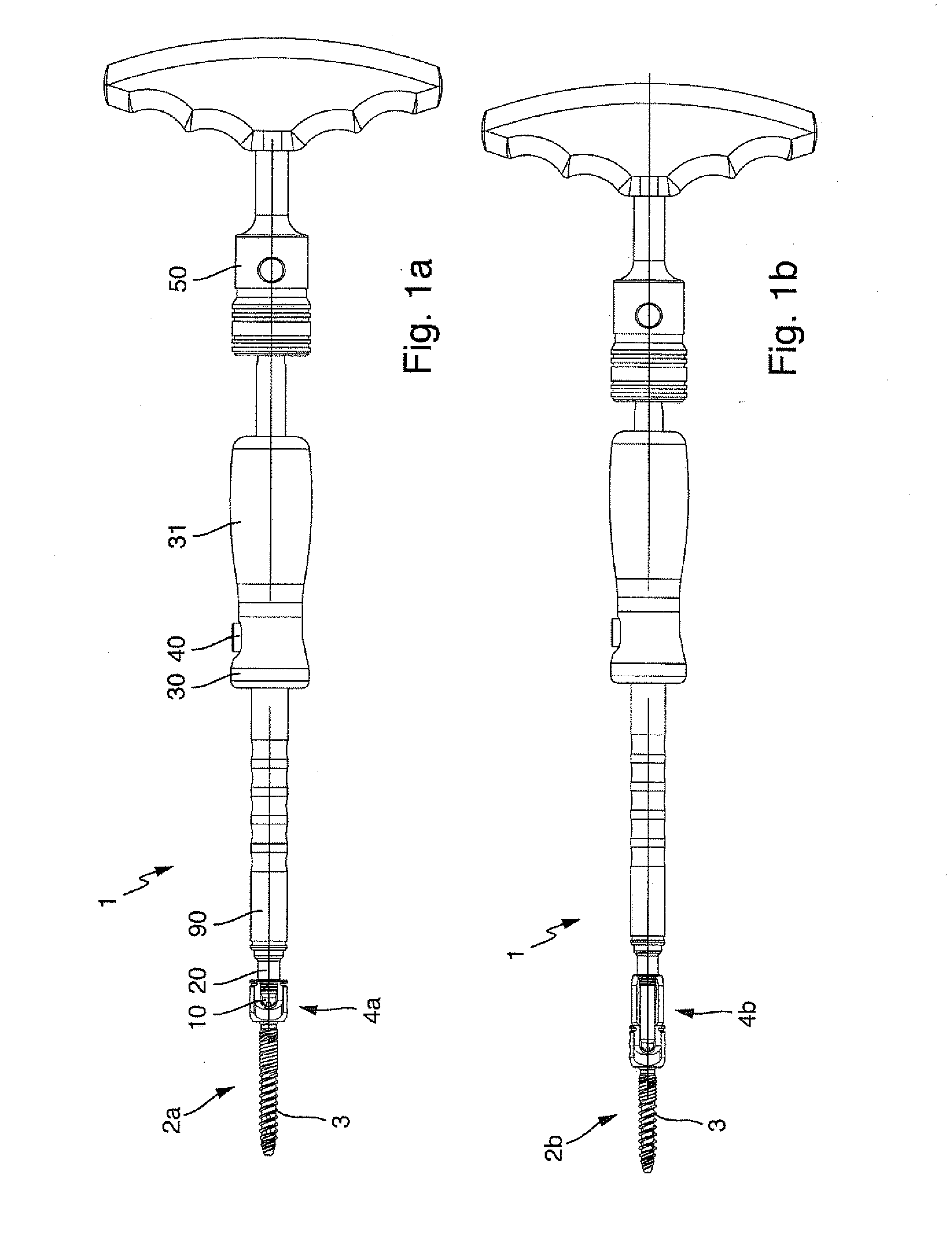
[0033]Turning now to the drawing, and in particular to FIGS. 1a and 1b there is shown in respective side views an exemplary embodiment of a screwdriver 1 according to the invention for bone screws 2a, 2b. FIG. 1 shows the exemplary embodiment of the screwdriver 1 according to the invention in an operating position for use in bone screws 2a with a short fork head 4a, i.e., a fo...


PUM


Abstract

A screwdriver for actuating bone screws which have a shaft and a fork head for holding a vertebral rot or the like, includes a central shaft, which at its distal end is provided with a formfitting or force-fitting profile for engagement in a corresponding counter profile on the bone screw for turning the bone screw, a distal sleeve which rotatably engages around the shaft and is provided with connecting means for holding the screwdriver on the fork head of the bone screw, a handle provided at the proximal end of the screwdriver and a turn handle which is connected with the distal sleeve, and an adjustment device for axial adjustment of the relative position of the central shaft relative to the distal sleeve in at least two different predefined positions which are adjusted for different sizes and shapes of bone screws.

Description

CROSS-REFERENCES TO RELATED APPLICATIONS[0001]This application claims the priority of German Patent Application, Serial No. 20 2013 004 369.5, filed Apr. 29, 2013, pursuant to 35 U.S.C. 119(a)-(d), the disclosure of which is incorporated herein by reference.BACKGROUND OF THE INVENTION[0002]The present invention relates to a screwdriver for actuating bone screws.[0003]The following discussion of related art is provided to assist the reader in understanding the advantages of the invention, and is not to be construed as an admission that this related art is prior art to this invention.[0004]Bone screws are screwed into a bone at a desired site, for example a vertebral bone in the body, and serve for fastening of for example a vertebral rod. The vertebral rod is fastened between multiple such screws at their fork head which is provided therefore. These bone screws usually have a threaded shaft and a fork head in the form of fork-like protruding legs, between which the vertebral rod is f...

Claims


Application Information

Patent Timeline
Patent Type & Authority Applications(United States)
IPC IPC(8): A61B17/88
CPCA61B17/8886A61B17/7082A61B17/8891B25B15/02B25B23/101
Inventor HEUER, FRANKTRAUTWEIN, FRANK THILOFROMM, MICHAEL
Owner SILONY MEDICAL INT
Why Eureka
Try Eureka