Electrically drivable valve for regulating volume flows in a heating and/or cooling system of a motor vehicle

a technology of electric drivable valves and heating and cooling systems, which is applied in the direction of multiple way valves, mechanical equipment, engine cooling apparatus, etc., can solve problems such as pressure losses in control circuits, and achieve the effect of reliable reduction of pressure losses

Inactive Publication Date: 2014-11-06
BEHR THERMOT TRONIK
View PDF8 Cites 1 Cited by
  • Summary
  • Abstract
  • Description
  • Claims
  • Application Information

AI Technical Summary

Benefits of technology

[0012]It is therefore an object of the invention to provide an electrically drivable valve for regulating volume flows in a heating and / or cooling system of a motor vehicle, said valve which assures a reliable reduction of pressure losses in the control circuit.

Problems solved by technology

Depending on the structural design of the valve, pressure losses arise within the control circuit.

Method used


Image

  • Electrically drivable valve for regulating volume flows in a heating and/or cooling system of a motor vehicle
  • Electrically drivable valve for regulating volume flows in a heating and/or cooling system of a motor vehicle
  • Electrically drivable valve for regulating volume flows in a heating and/or cooling system of a motor vehicle

Examples


Embodiment Construction

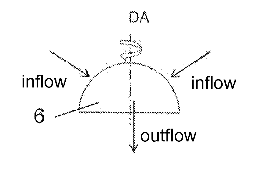
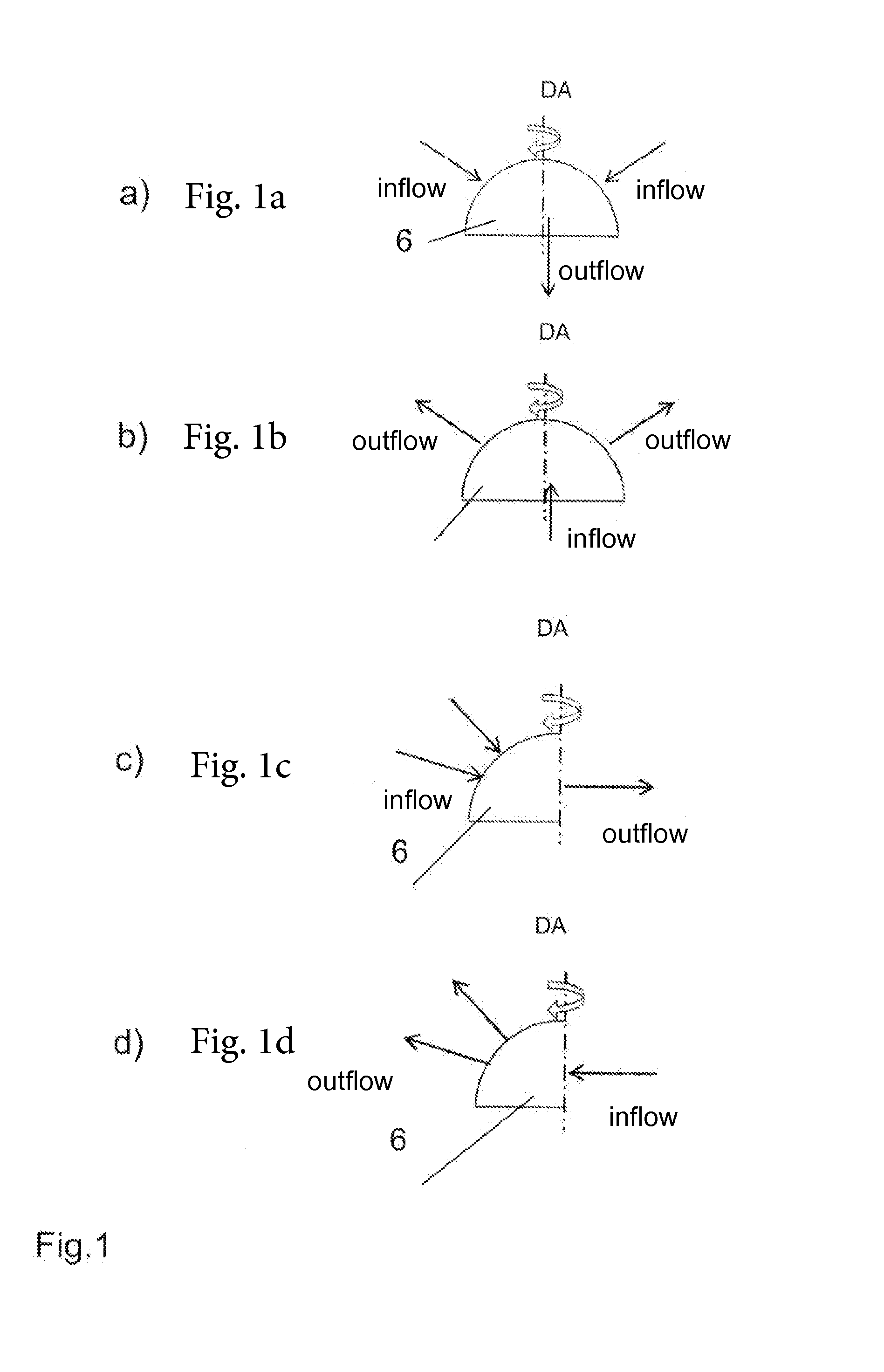
[0029]The inflows / outflows in a hemispherical valve body 6 are shown schematically in FIGS. 1a and 1b. In FIG. 1a, the connecting piece for the inflow is arranged between an axial and radial orientation relative to the rotation axis DA of valve body 6, whereas the connecting piece provided for the outflow is formed axially to the rotation axis DA of the valve body. This mode of action is realized in a valve as an ingress regulator. In the design of the valve as an egress regulator, an axial inflow occurs through the one connecting piece, whereas the further connecting pieces are formed as outflow fittings, which are also formed between an axial and radial orientation to the rotation axis DA (FIG. 1b).

[0030]In FIG. 1c, valve body 6 is formed as a spherical segment, for example, as a quadrant of a hemisphere. In this regard, the inflow fittings used for the inflow are located next to one another on a valve housing area adjacent to the spherical segment, formed as a quadrant of a hemis...


PUM


Abstract

An electrically drivable valve for regulating volume flows in a heating and/or cooling system of a motor vehicle with a housing, on which at least two connecting pieces are formed, whereby depending on the arrangement of the valve in a heating and/or cooling circuit one or more connecting pieces are formed as inflow connections and a connecting piece as an outflow connection or one or more connecting pieces as outflow connections and a connecting piece as an inflow connection, whereby a valve body rotatable around a rotation axis is arranged in the housing. In the case of an electrically controllable valve, in which pressure losses in the control circuit are reliably reduced, in the case of an axial inflow or outflow of the valve by a heating medium and/or coolant the axes of one or more outflow connections or of one or more inflow connections are oriented axially and radially relative to the rotation axis of the valve body.

Description

[0001]This nonprovisional application claims priority under 35 U.S.C. §119(a) to German Patent Application No. 10 2013 208 193.6, which was filed in Germany on May 3, 2013, and which is herein incorporated by reference.BACKGROUND OF THE INVENTION[0002]1. Field of the Invention[0003]The invention relates to an electrically drivable valve for regulating volume flows in a heating and / or cooling system of a motor vehicle.[0004]2. Description of the Background Art[0005]Thermal management in a cooling system plays a major role in today's motor vehicles, particularly with respect to reducing fuel consumption, reducing CO2 emissions, and increasing comfort. In this regard, fluid flows are switched or regulated depending on the thermal requirement, thus, e.g., in the case of coolant stoppage during warm-up or according to the load conditions of the internal combustion engine. Electrically drivable valves with highly different design types are employed for switching and regulating the fluid f...

Claims


Application Information

Patent Timeline
Patent Type & Authority Applications(United States)
IPC IPC(8): F16K11/02
CPCF16K11/02F01P7/14F16K11/0876Y10T137/86863
Inventor KLEIN, HANS-PETER
Owner BEHR THERMOT TRONIK
Why Eureka
Try Eureka